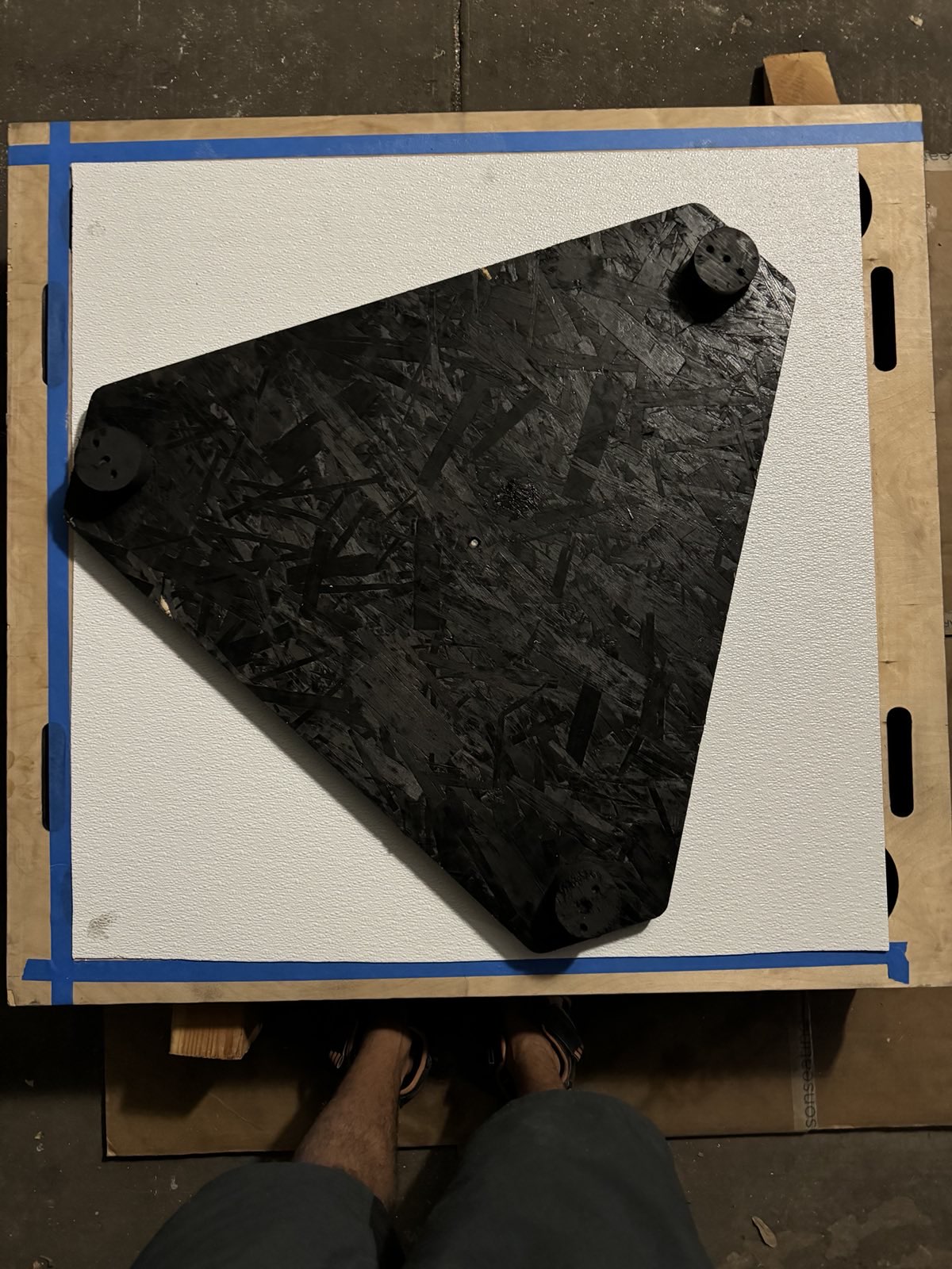
A first look at the well-preserved mirror
(To see the full-size version of any picture, right click and open the image in a new tab)
Firstly, the history of the telescope and what existed before I restored it:
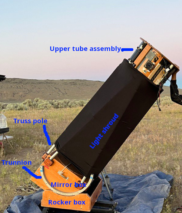
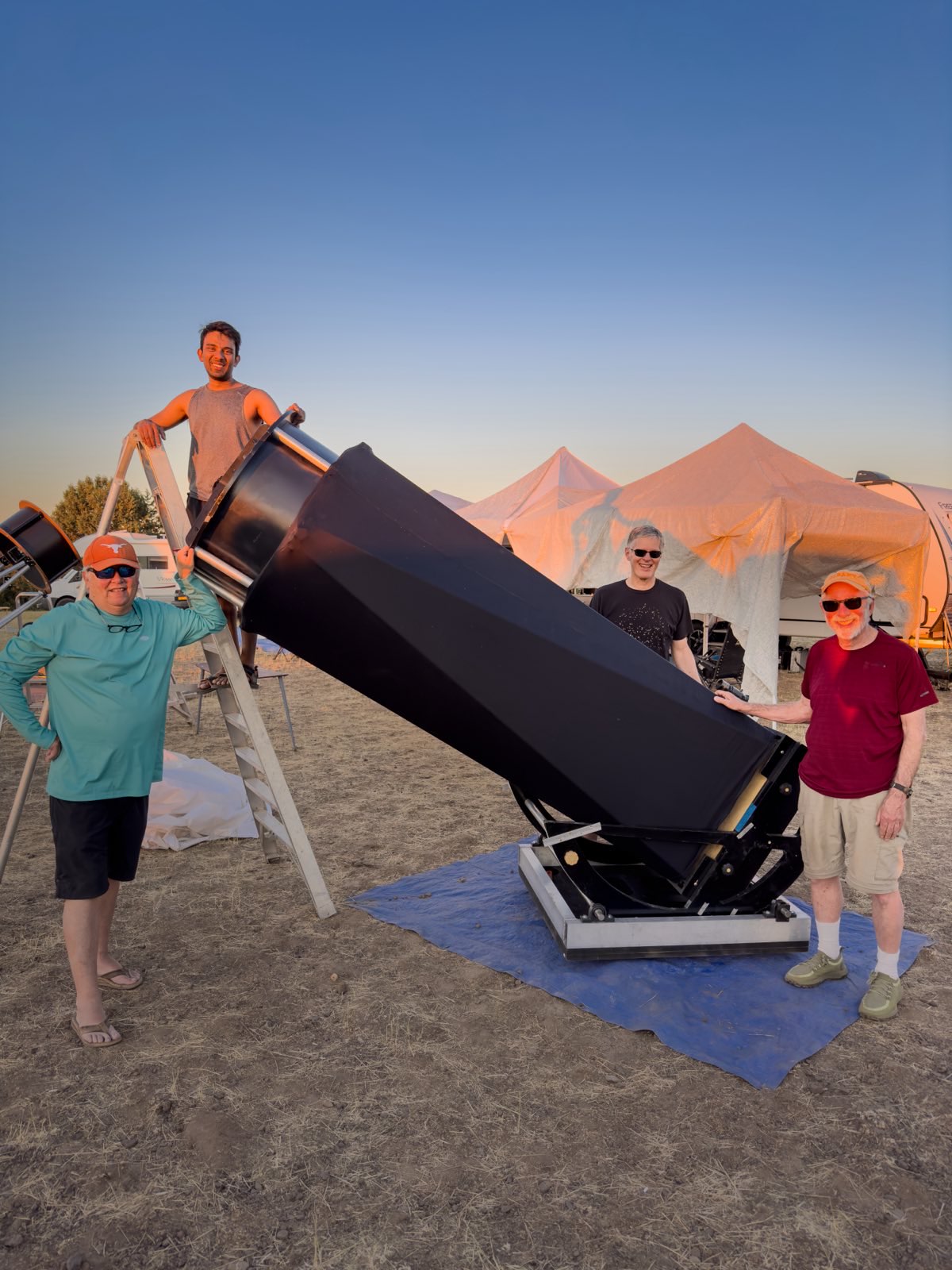
I wrote this text for someone who already knows enough about Dobsonian telescopes and their parts. If you are not familiar with the terms used for various parts of a Dobsonian, look at the picture on this website—it labels all the major parts. Sometimes the secondary cage is also called the "Upper Tube Assembly" (UTA) for short, and the two crescent-shaped arcs that form the moving part of the altitude axis are called "altitude bearings" or more appropriately "trunnions". For your convenience, I also labeled the parts on my 18-inch telescope. Also, when we specify a measurement for a telescope in inches, we are generally talking about the diameter of the primary mirror which is the main light-gathering element. The number specified alongside it with an f/-prefix, known as the "f-number" is the ratio of the focal length to the diameter.
In April 2022, I took a pilgrimage to Jimi Lowrey's observatory to enjoy several nights with his incredible 48-inch f/4 telescope. (Click here for some sketches of what I've seen through this incredible telescope.) Normally, we west-coast amateur astronomers fly to an airport and rent a car to make it to Jimi's observatory, but this time I drove my pickup truck (a Toyota Tacoma) so I could haul some stuff back! Howard Banich and Steve Gottlieb were also at Jimi's place and they helped me load the mirror and existing parts into my truck.
We placed the mirror in its mirror box, and the mirror box on wood 2×4s in my truck bed. The trunnions rode in the bed, as did the truss poles which had to be fit diagonally—I did not have the right hardware to tie the truss poles to the roof of my truck cap. The upper tube assembly rode in the back row of my cabin with the seat folded down—Toyota has really thought through when it comes to making the cabin usable for hauling. The rear suspension on my truck is a leaf spring and although the ride is rough, it is not too rough for 2" thick glass—properly annealed mirrors are generally rugged when transported in their mirror cells.
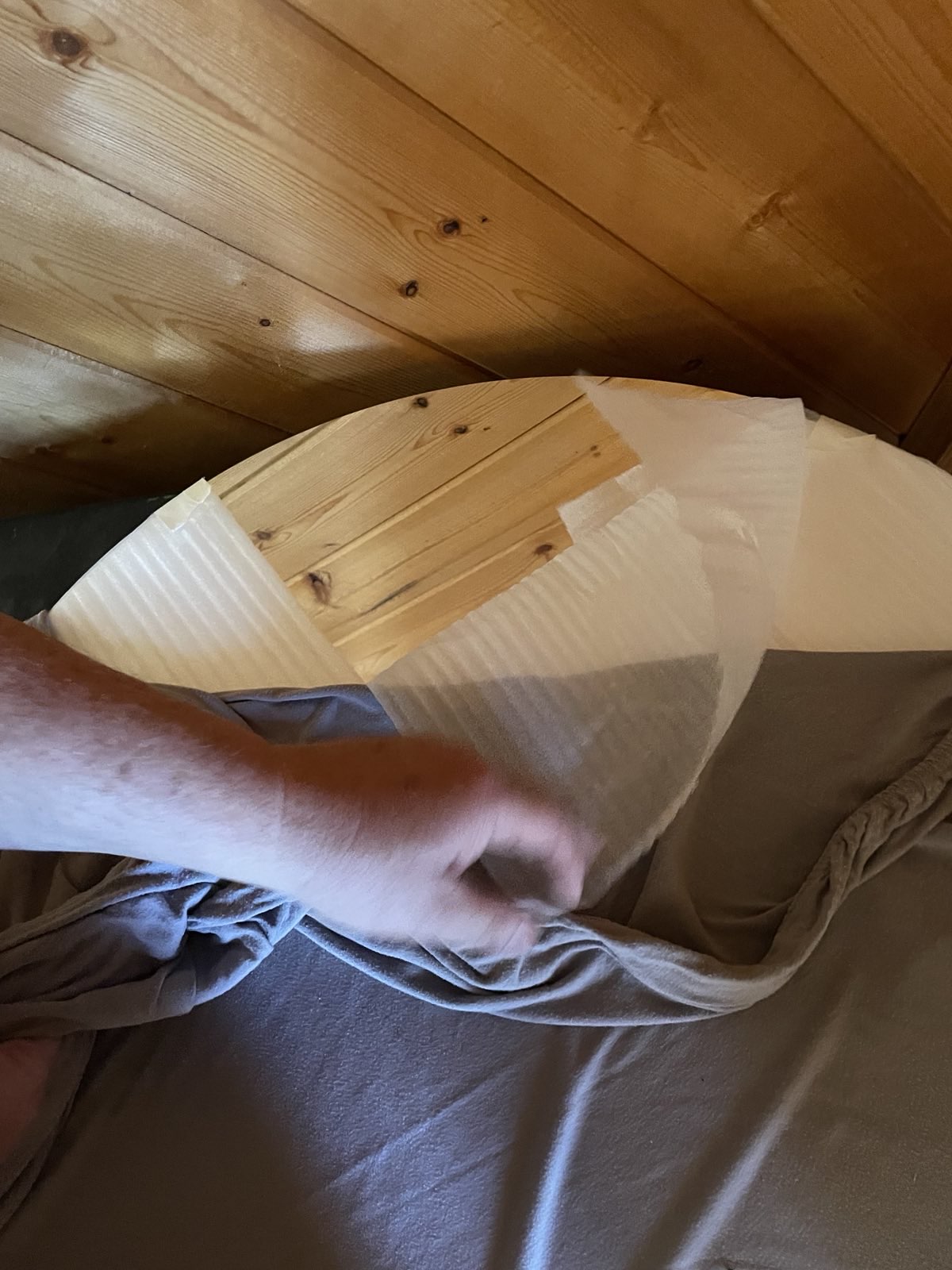
Jimi also gave me various accessories he had, such as the light shroud and dust cover from AstroSystems. The secondary mirror was not installed in the spider, so I carefully wrapped it in soft tissue paper and packed it in cardboard to protect it. Most amateur astronomers use a velvet bag like the one made by Crown Royal for their whiskey bottles to prevent scratching the mirror surface. Jimi had given me a crown royal bag, but I did not realize this, so I came up with the tissue paper method.
Following Howard's advice to make an accurate CAD model worked well for me
A couple of months in the laboratory can frequently save a couple of hours in the library.
—Dr. Frank Westheimer
I was very excited about the new telescope, and started making a CAD model of the telescope per Howard Banich's suggestion. I run the ArchLinux operating system on my computer, which constrained my possible CAD software options. I had never used FreeCAD before and watched several YouTube tutorials to pick it up. The idea of parametric CAD is fascinating, I made sure to do all my computations in a spreadsheet and pick up dimensions from it in my sketches.
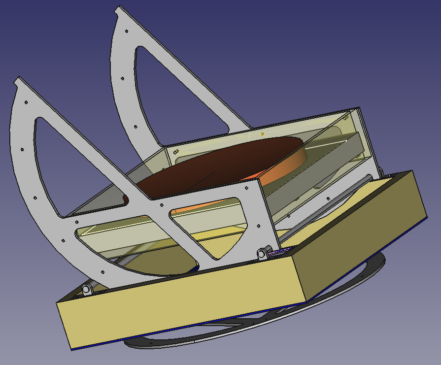
Since it was my first time using FreeCAD, I did not make correct use of all of its tools and ran into several problems. I never perfectly finished a full CAD model of the telescope, but I did make a partial model. I eventually learned to use the Assembly4 Workbench to put it together. The partial model helped tremendously to ensure that the mirror box would not interfere with the bottom of the rocker box, such that we were able to place the bearings at the calculated position and get a working altitude movement without needing to shave the mirror box down.
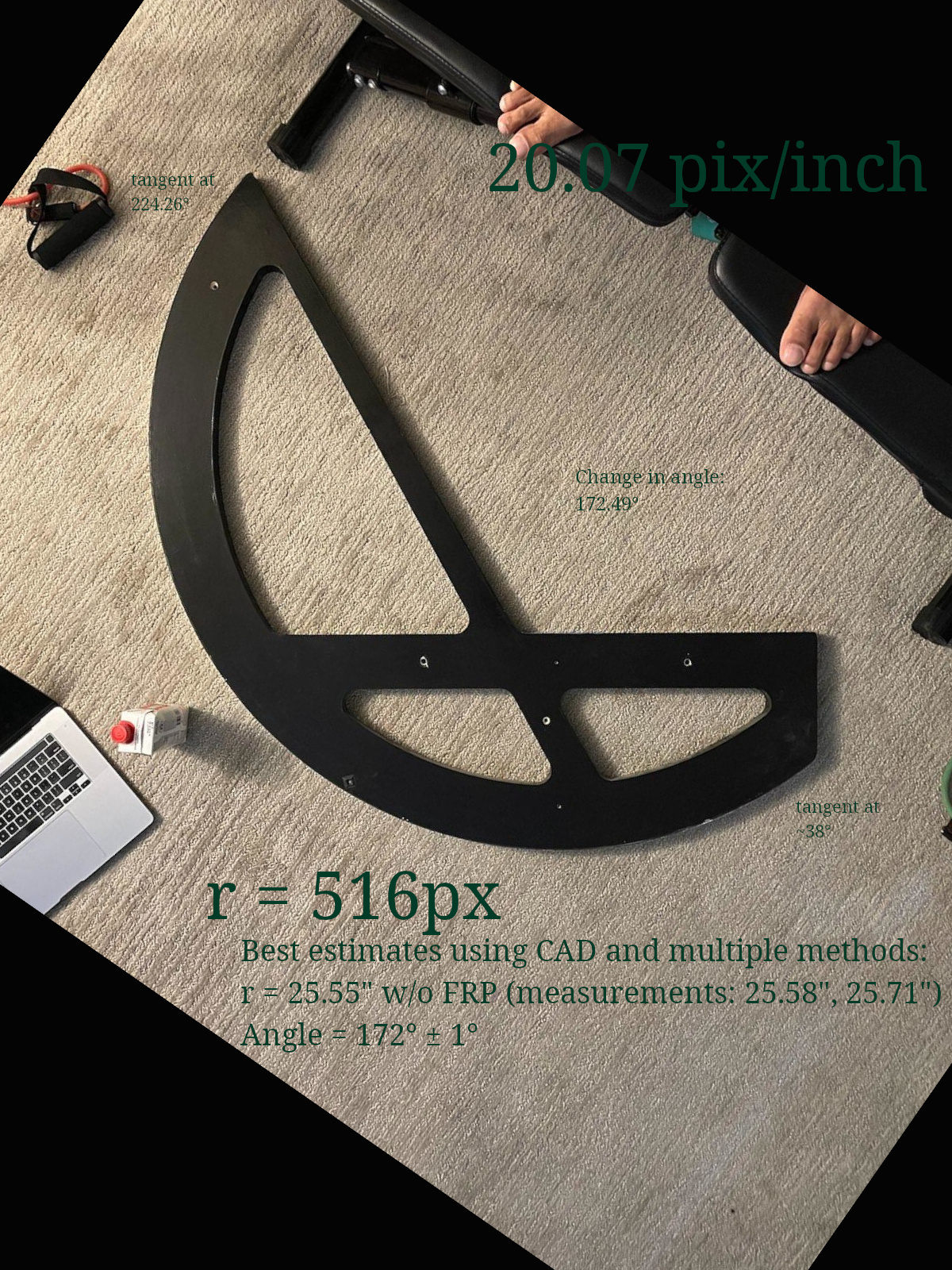
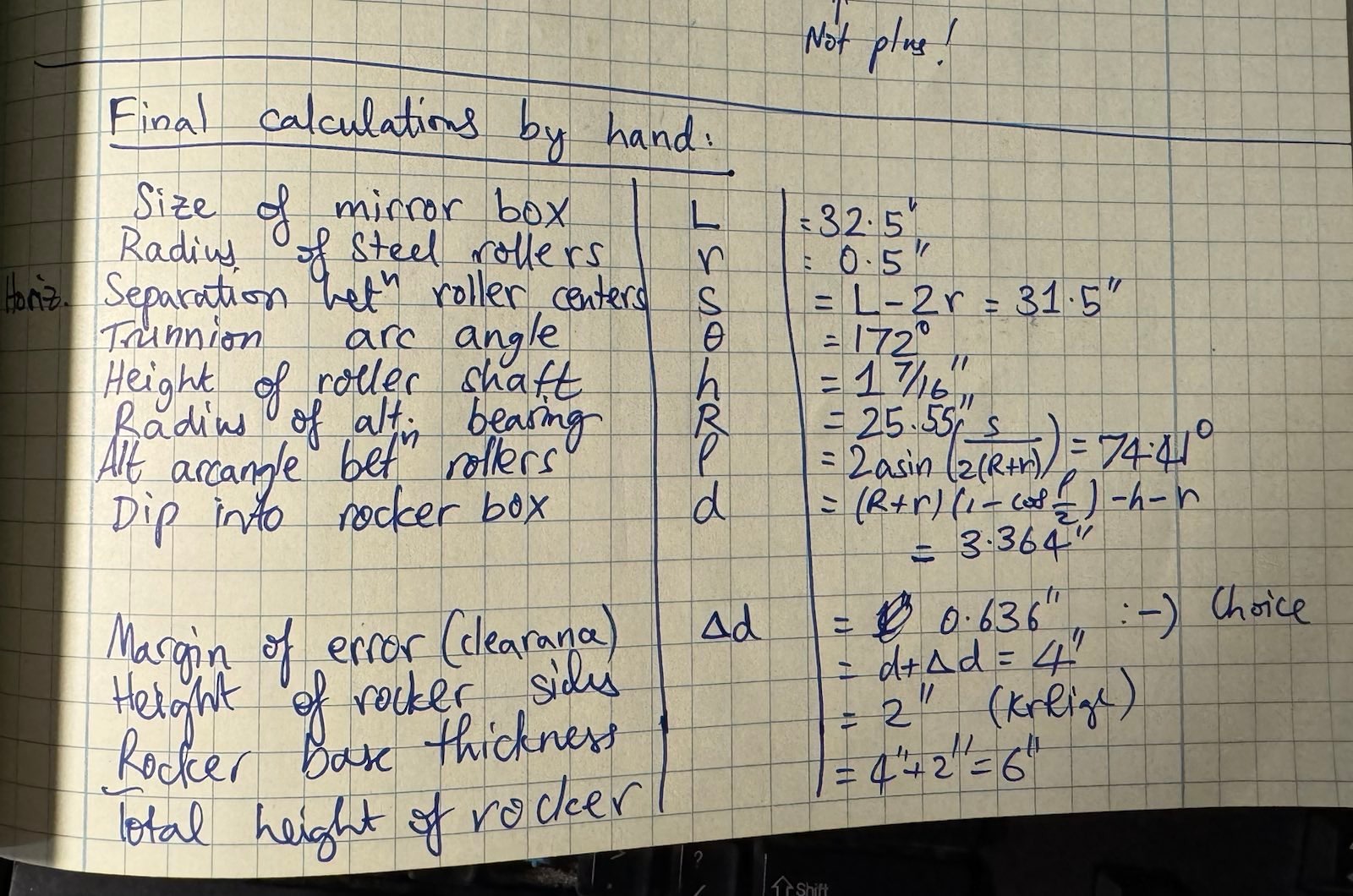
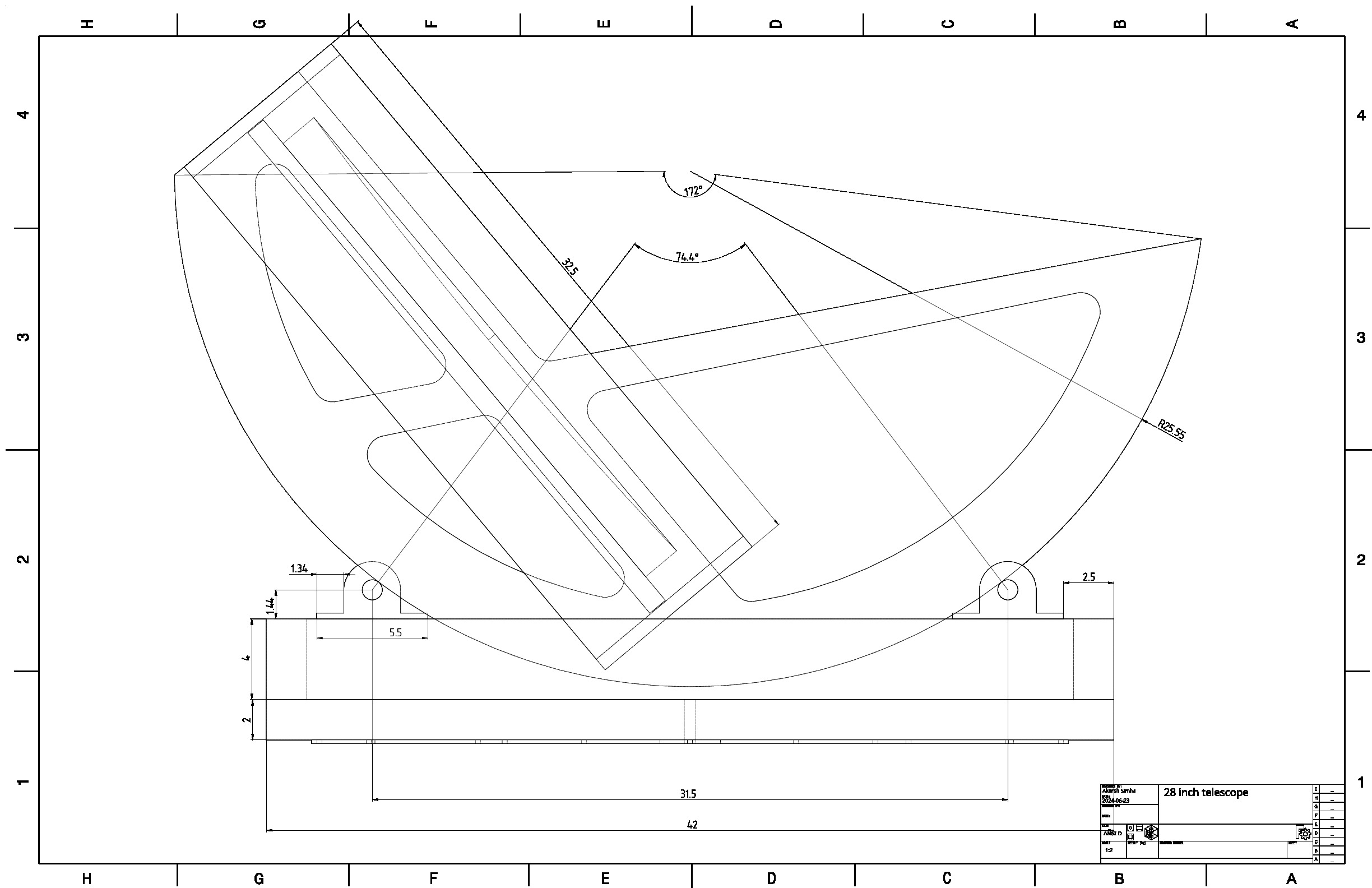
I spent a good chunk of time measuring the dimensions of the existing parts using multiple methods. One of the tricky ones was to verify that the radius of the trunnions was 25.55" per Howard's design (It's only after that I learned that Jimi used exactly Howard's design to-scale — I don't know why I didn't ask him first). To measure the radius, I measured a chord from two ends of the bearing, and then measured the perpendicular distance . Then I calculated the radius of the circle using This method gave a very accurate result and verified the bearings had R = 25.55", Howard's dimension.
I fed the measured dimensions into the CAD model spreadsheet and visualized the result. I also did a bunch of math to see how to fit it into my truck, but I don't think it was accurate. In any case, doing everything once by hand stimulated my visualization to make sure the scope would work.
The original telescope was built to ride on teflon pads with a curved rocker-box wall like a typical Dave Kriege dob. My aim was to instead design it to run on rollers like Howard Banich's or Tom Osypowski's telescopes. So the key parameters I had to tack down was the internal height of the rocker box and the separation between the rollers. If the internal height was too little, the mirror box would hit the base of the rocker box and be unable to move. If the separation between rollers was too large, the telescope would not point to the zenith with the way the trunnions were designed. If it was too small, the scope would be less stable, be unnecessarily tall, and would have too much altitude travel.
The side of the mirror box was 32.5". I figured that the trunnions were designed so that the separation between the 1" roller centers must exactly be equal to 31.5" so that their outer edges are 32.5" apart. This may have been obvious to others, but I had to think quite a bit about it! This way the scope would be able to point to the zenith since the trunnion's end coincided with the wall of the mirror box. I entered this into CAD and visualized it for clarity and to ensure no interference with the rocker box base!
As I went about building the telescope's parts, I divorced myself from the full 3D CAD build and made separate CAD models for sub-assemblies, because wrangling the big telescope CAD was rather much, and FreeCAD can be unstable. I must say that despite its few drawbacks, for a free volunteer-driven CAD modeling software, FreeCAD far exceeds my expectations and is a testament to the power of the open source community and the passion of volunteers.
I am reminded of Dr. Frank Westheimer's quote, because spending time on checking and visualizing the design before each step helped ensure that things worked correctly at almost every stage of this build process. The equivalent here is that an hour of planning and designing—be it on CAD or paper—can save a lot of trouble and wasted material.
I've usually found procrastination to be a powerful way for the subconscious to do its thing, and in my experience it certainly helps with telescope making.
—Howard Banich
Once the initial excitement faded, I procrastinated on the project for the subsequent two years! This was partially because of personal life constraints, and partially because I was intimidated by the difficulty of taking up a project in a domain where I had virtually no experience. I'd like to think that some progress occurred passively during this period, as Howard Banich says.
In June 2024 I visited Jimi's place for a week. We didn't have the best conditions, but we still got a couple nights of decent observing. The main fruitful development that occurred here, was that Jimi and Connie Lowrey were able to motivate and encourage me to try build a rocker box for the telescope before the Golden State Star Party (GSSP) in July 2024. I only had about 3 weeks of time! Thanks to Jimi's simplifications of the ideas and help with project management, we were able to lay out a plan which would get us first light by GSSP. Jimi took off one major step by loaning me his really nice ladder, which I brought to California in my truck.
The idea was to build a rocker box that was a composite of aluminum and wood, keeping things as simple and easy as possible. The altitude bearing would have the final form desired except without the drivetrain, i.e. trunnions riding on stainless steel shafts that are supported by pillow block bearings just like Howard Banich's design. The azimuth bearing however, would be a Kriege-style FRP/teflon system. The ground board therefore would be a "throwaway" construction with the teflon pads, something that would be replaced after the drivetrain is built. This way, we didn't have to do a bunch of metal fabrication for the azimuth bearing and could build the telescope entirely from off-the-shelf components, except one welding job.
Jimi's advice: Touch and feel the raw materials
Initially, we were going to have the rocker box be an aluminum frame made of C-channels, with Baltic Birch plywood base of appropriate thickness fastened using countersunk flat-head screws to the frame. The ground board could be made from any cheap plywood since it wasn't subject to any shearing loads—see Kriege and Berry §10.2.1—I would make wooden feet for the ground board and place the teflon pads right above the feet to avoid any shearing force.
We started making a shopping and task list. I had to find a supplier of aluminum C-channels, locate a welder skilled with TIG welding of aluminum, find a plywood supplier for Baltic Birch or ApplePly, find a fastener store, etc. I was recommended to avoid speculative online shopping and instead go see, measure, touch and feel the raw materials—very good advice.
You can buy metal in many forms: bars a.k.a. rods (rectangular, square, flat, round) which are solid; tubing (rectangular, square, round) which is hollow; and U-, L- (a.k.a. angle stock) and C- channels. I quickly found out that Aluminum C-channels, also known as structural channels, were quite expensive. We wanted the American Standard profile instead of the Aluminum Association profile because it had more buttresses to take the > 150lb (70kg) load of the telescope above, and this was also hard to come by. Jimi taught me that structural channels are different from the more commonly available U-channel, which does not have a buttress. Compare them here. If you want to see the various profiles, a good place to check them out is OnlineMetals.com's weight calculator.
Check stores for remnant (discarded cuts of high-quality metal) and scrap (junk) metal, as they are generally cheaper and sold by weight
I found out instead that Aluminum rectangular tubing was affordable and readily available, and it was in stock at one of the best metal shops (recommended by Randy Pufahl and Charlie Wicks) in San Jose. A quick check with Howard Banich indicated that his rocker box frame, too, is made from rectangular aluminum tubing, 2" × 4" × ⅛". These dimensions worked well for me and since they were already tried and tested by Howard for his 28", I decided to go with them. The metal shop I used, Industrial Metal Supply Co., was able to do cuts for a modest fee. This precluded the need to find a band saw. They also gave me a first-order discount for opening an account with them. They recommended an aluminum welder for me, Mr. Dave Stickles. Fortunately for me, Dave had the ability to give me a fast turnaround time at a very good price. His team's timely TIG welding work was crucial to the success of my project.
I determined the dimensions as follows: the mirror box is 32.5" square. Each trunnion is 1.25" thick. Therefore the inner dimension of the rocker box should be at least 35". With a 0.25" margin on either side, we should have at least 35.5". I chose to increase the buffer for added margin and made it a round 36-inches. This means the outer dimension was 40" along the direction of the roller shafts.
For the other dimension perpendicular to the direction of the roller shafts, I chose to have extra room so that I had more space to mount various electronics and drive-train components without worrying about interference from the mirror. Thus, I made them 42" outer instead of 40". It is possible I could have even gone shorter, down to 38" outer dimension—but anything shorter would have had the flange of the pillow block bearings protruding. In any case, I figured the weight cost of this decision was marginal, and the dimensions would still fit in my truck bed in either orientation.
The vertical clearance margin I had calculated was a bit over half an inch, and I did not want to have any more buffer there. For some reason, after assembly, it turned out that I had more vertical clearance between the base of the rocker and the mirror box and I don't fully understand why. This was undesirable as I wanted the system to be as low profile as possible to fit the lower assembly in my truck bed without disassembly, something I still haven't achieved.
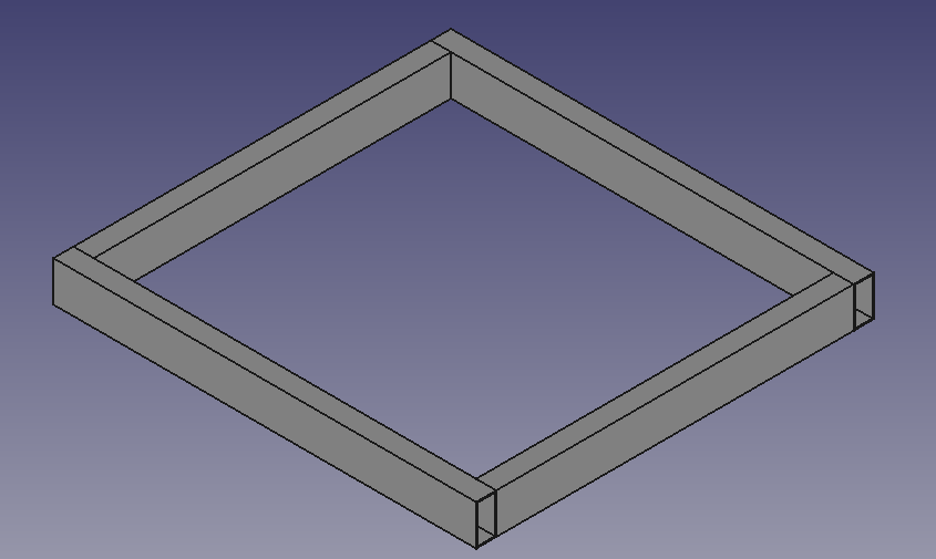
Therefore, I ended up with a 40" × 42" rocker box. I drew it up in FreeCAD once again for visualization. It did help me catch a few errors I would have made otherwise owing to inexperience. It was important for me to visualize the rectangle built from the tubing so I could ensure that I got the cuts right: two pieces 42" long and two pieces 36" long. This way, no weld joints would protrude under the pillow-block bearings. The load would not be spread across two pieces of tubing and the perpendicular members would act as support. This seemed cleaner to me than laying out four 40" long tubing pieces. As an added bonus, the two long members would be able to take wheel-barrow handles through them just like in Howard's setup.
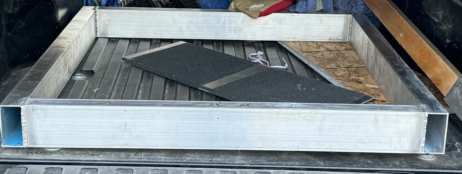
The cuts were made and I took the pieces to Dave. Dave carefully laid them out on his driveway to understand the orientation and marked them up so they would weld it up correctly. I didn't exercise a preference on which sides could be welded (in fact I wanted it as strong as possible), so they went over and above the requirement and welded on all four sides of each joint. Generally, welded joints are stronger than the base material! Perhaps in hindsight, I should have preferred the welds to be on the top and on the inside and/or outside of the frame but not the bottom, so that the wood would sit flush without the weld joint sticking out. Thankfully, wood can compress so this was not an issue.
"Building a telescope means it's never finished, so don't worry about getting everything perfect on your first go. And just getting started will snowball your motivation."
— Howard Banich
Most telescopes are made from one of these three plywood materials: Baltic Birch, ApplePly and EuroPly. The reasoning seems to be that they are strong, have multiple plies for stiffness, are free from voids, stain well, etc. I was told that they are also harder to delaminate if properly treated. Apparently you can use cheaper plywoods. As a person who has little background in building stuff, you want to err on the side of success at least for your first build right? I went with the standard wisdom and paid through my nose for expensive Baltic Birch.
Kriege and Berry emphasize the importance of a stiff rocker box in their book all through. They explain with equations in Chapter 3 that flexure increases as the cube of the length of a cantilever beam, making the demands on bigger telescopes more exacting. In Table 10.1 of the book, they recommend a 1.5" to 2" rocker box base thickness for a 28-inch dob. I heard opinions from more experienced friends—some recommending that I stick by Kriege's recommendation, some opining that it was overkill. Of course, Kriege's recommendation treats a pure wooden rocker box, not a wood-aluminum composite like the one I was building.
I should mention that in the process I learned of Mel Bartels and Dan Gray's invention of the "flex rocker". The flex rocker is a very low profile rocker box which is not designed for stiffness, and just like the ground board in a Kriege-style telescope, it's job is to transmit the forces down without shearing loads. It therefore has four points of contact with the azimuth bearing, two below each trunnion. My understanding is that the low profile makes the flexure of the rocker box produce insignificant bounce-back at the eyepiece. I believe this requires the trunnions to be larger.
I wanted a working telescope first, not an optimal one. I loved Howard Banich's advice: "Building a telescope means it's never finished, so don't worry about getting everything perfect on your first go. And just getting started will snowball your motivation." I decided to err on the side of caution and go with a 2-inch thick base. It is certainly overkill and cost me more in terms of money and weight, but I had a fully working telescope without any iterations.
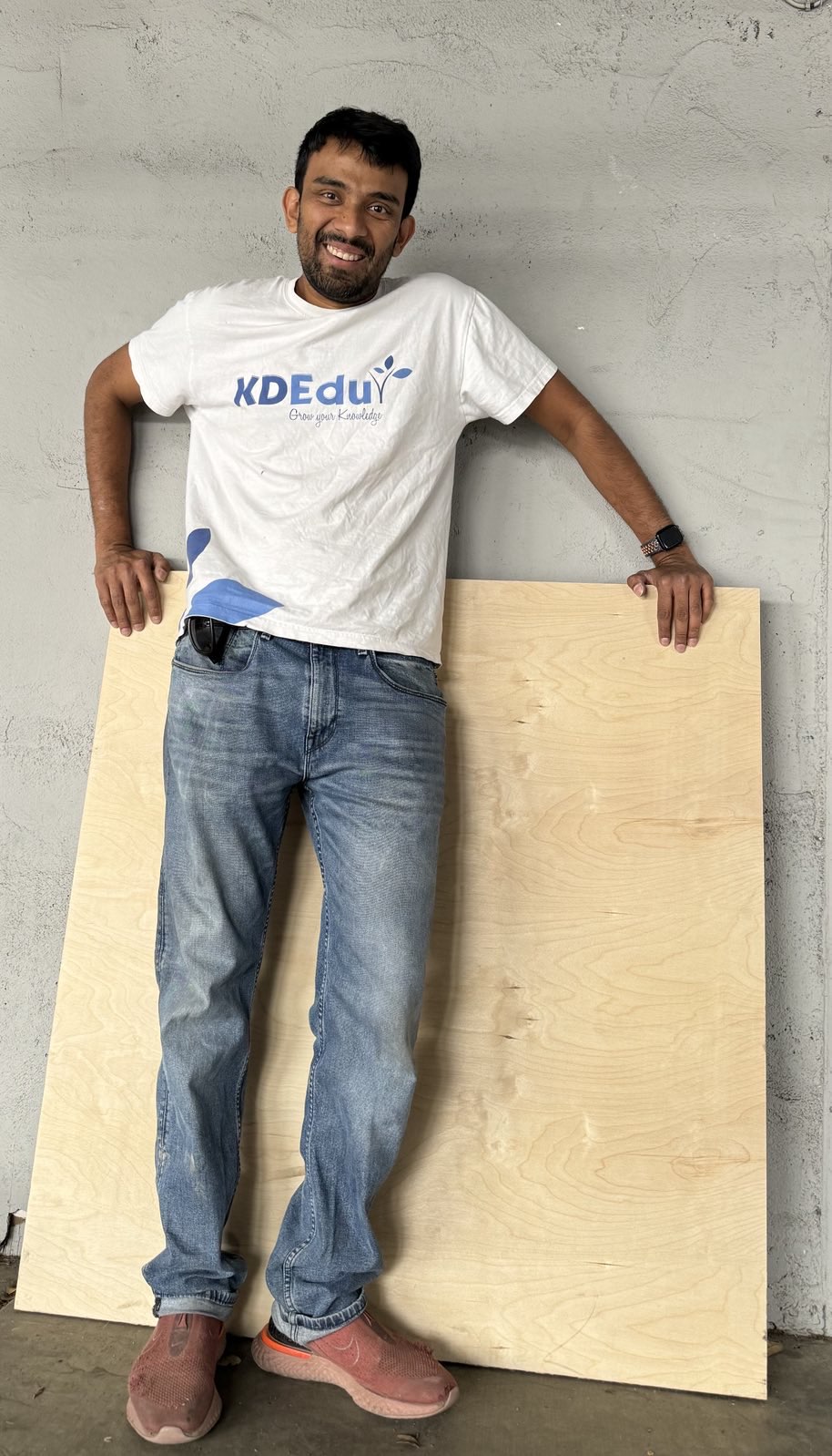 Baltic birch for the base after being cut to 42" × 40" — the first "oops, this is huge, what have I done!" moment.
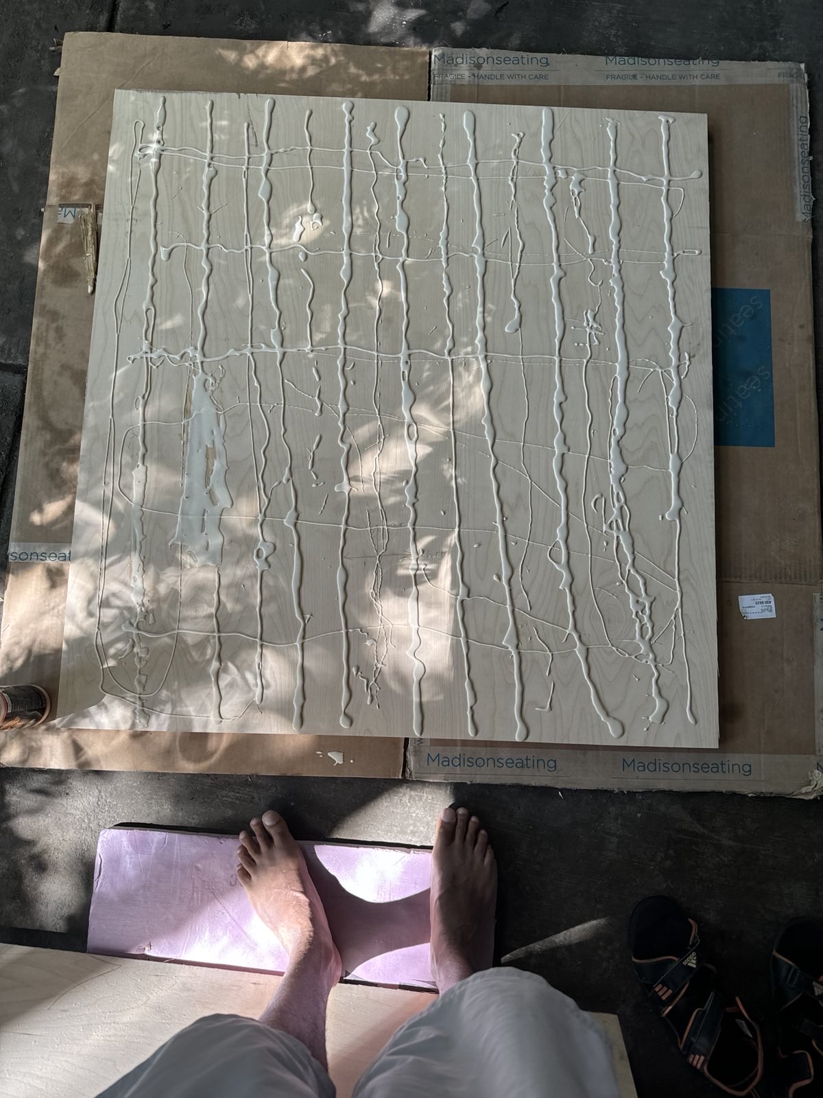 Applying wood glue to the boards.
Mark Wagner recommended me a lumber store, Hardwoods. They were one of the few that stocked thick Baltic Birch in the south bay, but they would not do cuts: this means I had to buy a 5' × 5' sheet of Baltic Birch. If I were to do this again, I would perhaps go to Pine Cone Lumber who can cut to size as it would have saved me trouble, although their Baltic Birch offering is limited to one thickness option. I bought two 5' × 5' × 25mm sheets (at 0.025lb/in³, this comes to 90lb per sheet!) and had them fork-lift it to the top of my truck cap. It's nice that the truck canopy is rated for 300+ lbs dynamic load, so the ~180lbs of those two sheets was well within rating. I secured the birch sheets carefully using ratchet straps and drove to a wood shop where Mark was able to help me unload the plywood and cut it to 42" × 40" on the table saw. We measured twice and cut. Each of the cut sheets was now something that I could lift by myself. Phew!
Now I was ready to glue the sheets of Baltic Birch together. I was about to use the Elmer's Wood Glue I had at home when I read its label and noted that it was "Interior" wood glue. Apparently, the wood glue for outdoor use is stronger and weathers better. To be on the safer side, I bought Gorilla Wood Glue "Ultimate" which is rated for outdoor applications and is waterproof.
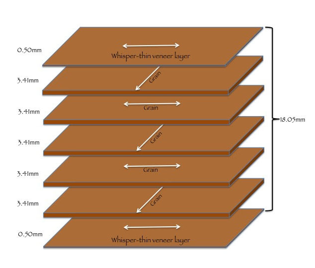
We were not very careful when cutting the sheets, but the grain direction on the two cuts ended up being perpendicular to each other. The grain direction is visible on the plywood as the direction in which the curved structures on the face of the plywood point. This was serendipitous since my rocker is rectangular and I could not simply rotate the sheets to match. This outcome is desirable as it creates perpendicularly oriented plies all through the stack. This would not matter a lot, especially with the many plies in the 2 inches of Baltic Birch.
I had bought myself a pack of Dewalt trigger clamps and used these as well as C-clamps. I let the adhesive cure overnight with plenty of clamp time and lots of weight placed on the boards. The weight was provided by kettlebells and camping water containers filled with water. Next morning I hand-sanded the minor misalignment out of the sides. I also sanded the edges and corners at an angle to chamfer them. Now once again, with the two boards glued together, the base became very heavy and difficult to lift by one person. I got a well-priced foldable dolly on Facebook marketplace to help me move the combination. I was able to dolly it down to my truck and lift it into my truck bed by standing it onto the tailgate and using the leverage to lift it up.
Fixing a wrong hole: If this is a pilot hole that's slightly off, it can be walked over a bit in the follow up holes of increasing sizes by attacking the surface at an angle and then straightening the drill. If this salvage cannot be made, get a dowel the next larger size, waller the hole out until the dowel fits snug, apply wood glue on the dowel and in the hole, hammer the dowel in with a mallet, saw off the excess, sand.
Lessons learned drilling: Recheck the measurement of a hole position before drilling multiple times and in different ways before commiting to a pilot hole. Use a small nail to make the starting hole (or use a spring-loaded punch which does not jump if working on metal). Start from a small drill and increase. Back through-holes in wood with scrap wood to prevent the work wood from splintering when the drill exits.
A Kriege-style central pivot is simply made with a ½"-13 bolt (see this table for a list of standard American thread specifications) that sits in a perfectly perpendicular and centered hole in the wooden base of the rocker box, with a washer to protect the integrity of the wood. On the ground board, there is a similar hole and a weld nut plate on the bottom side secured with wood screws. AstroSystems has a different pivot style: they use a Bronze bushing and a standard screw-on (round base) tee-nut. Mark Wagner's AstroGoods also sells pivot kits and he uses a teflon bushing—probably a better material—but his kits are for a 3/8" bolt which is recommended for the smaller dobs he normally works with. Perhaps I could have gotten away with a ⅜" bolt of grade 5, but I again wanted to trod the tested path.
I ended up using a bronze bushing and a ½"-13 tee-nut from McMaster-Carr. It was very hard to procure the ½"-13 tee-nut locally; most suppliers only carry up to 3/8". The bolt needed to be 4" long and I picked a standard ½"-13 zinc-coated steel hex bolt for this purpose. The screw on tee-nut took #8 wood screws and I picked up some stubby (¾" long) button-head ones at Pine Cone Lumber.
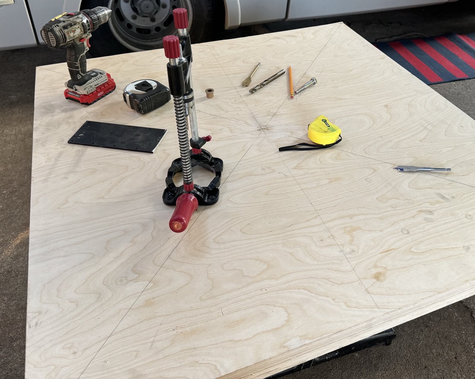
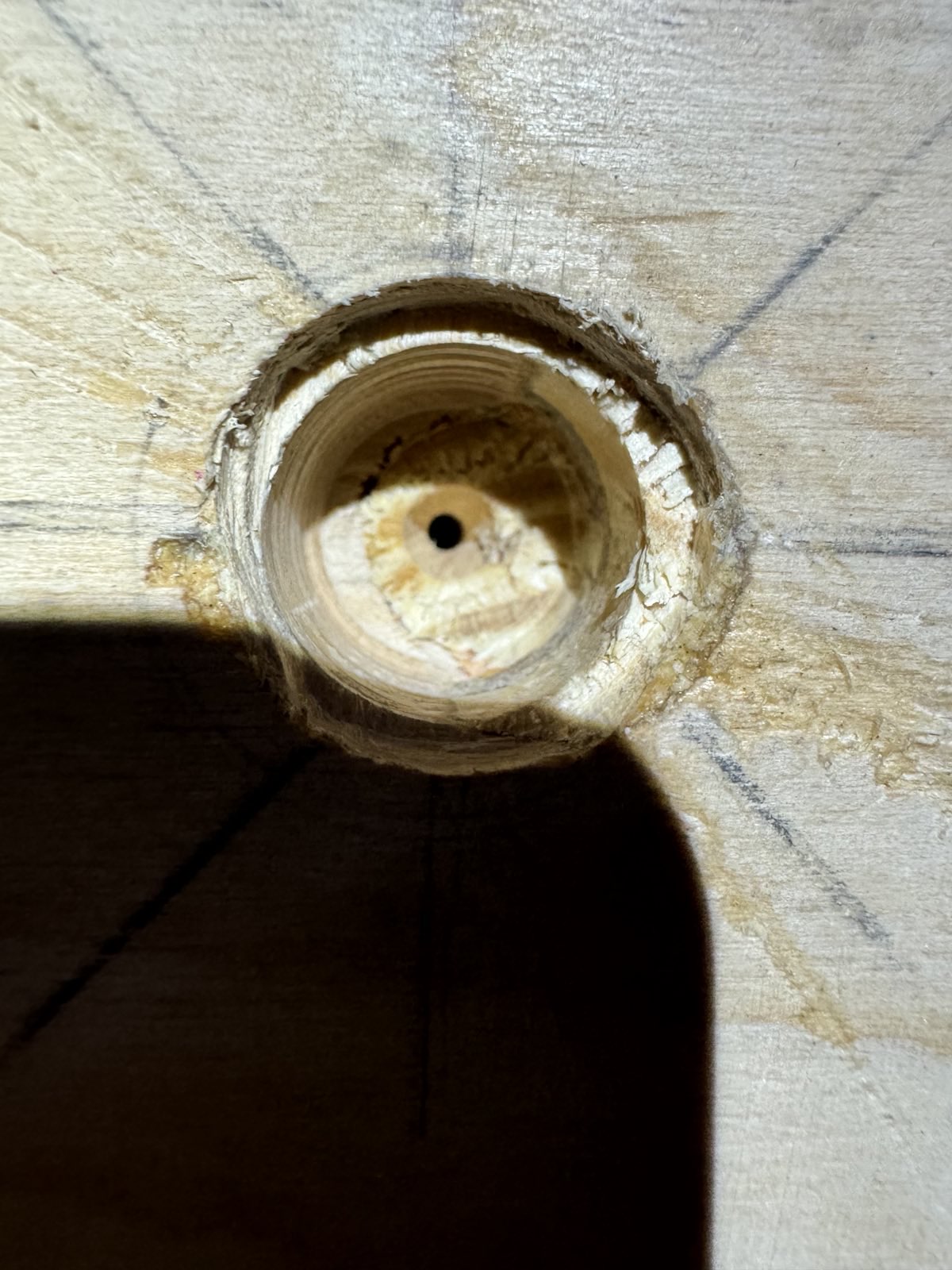
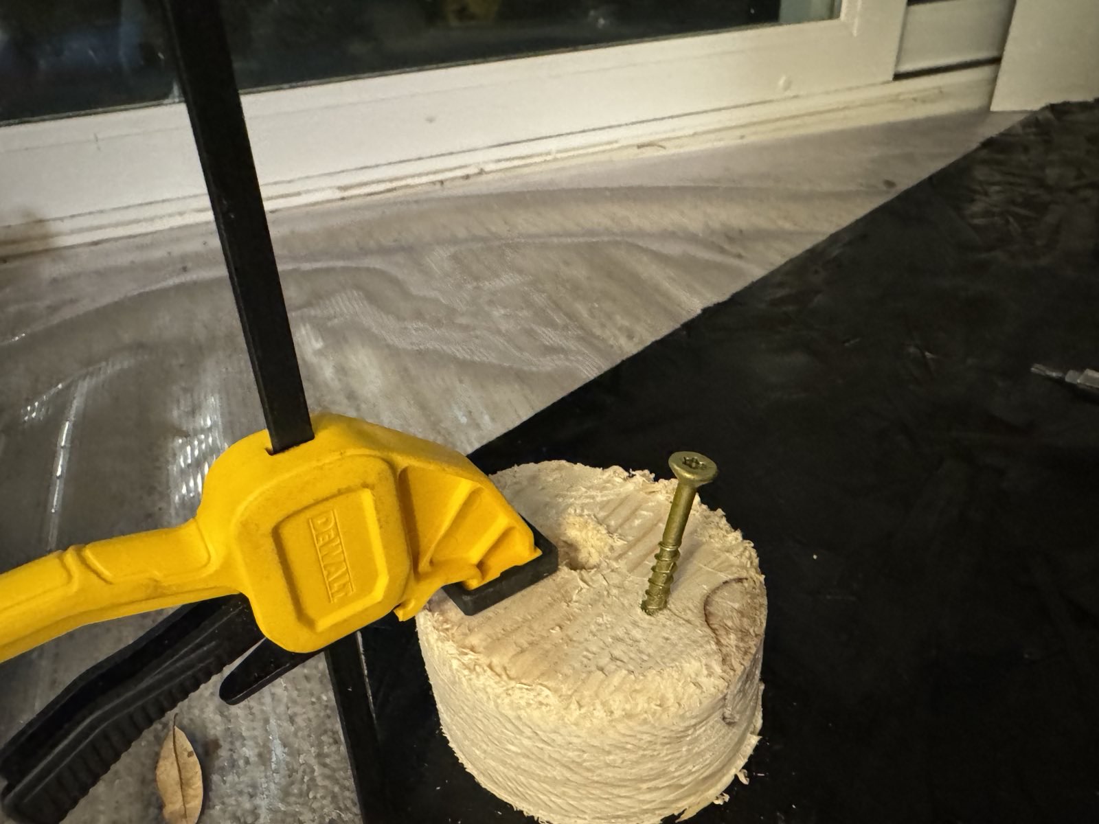
When I first drilled the center bolt hole in the rocker box base, I marked the center at the intersection of the two diagonals. I also did not do the drilling properly beyond that; my first drill bit did not center correctly, and then I tried to fight it and ended up with a hole that was not perpendicular. Both of these contributed to the hole not being in the center of the rocker box base. Even if the center pivot is not in the exact center, it most certainly has to be perpendicular — Kriege emphasizes this aspect in his book. So I had to fill in my mistake. I used a ½" drill bit in my hand drill to waller out the hole a little bit. A 5/8" wooden dowel was used to fill the hole: I chopped off a small bit of dowel with a hand saw, applied the Gorilla wood glue in the hole and on the dowel, and hammered the dowel into the hole once it would just fit. I used a regular hammer, but it would be smarter to use a mallet. Once the dowel was in the hole, I used the hand saw to cut the dowel as flush to the plywood as possible, and sanded it down and smeared some glue. It's important to note that the grain structure of the fix is not the same! See for example, this explanation. However, this fix worked perfectly for me and we were able to re-drill into the filled hole
I sought Randy Pufahl's help with this after I did it incorrectly. Randy had just returned from a vacation, but was already aware of my progress because he'd been giving me advice over text from a sailing adventure overseas! Firstly, we did the center mark properly this time — we marked off the mid-point (21") along the 42" dimension at three points along the 40" dimension, so that we could draw a straight line. We did the same with the other dimension. The point where the two lines meet is the center. We marked this and verified it once again. Then we used a small nail to create a divet at this location. We then used a ¾" spade bit in a drill guide to make the hole for the bronze bushing and drilled down to a bit over an inch to accommodate the length of the bushing. Taking a scrap piece of 2×4, we drilled a 5/8" hole in it and centered a piece of ½" ID copper pipe by wrapping tape on it for a snug fit. The copper pipe would guide our ½" spade bit for the bolt hole to ensure perpendicularity. We then used the spade bit and our eye to carefully center the copper pipe over the drilled hole, then drilling through with the spade bit guided by both the drill guide and the copper pipe. Next, placing the bushing in the hole, we hammered it in until it was flat. But putting a bolt through it showed that it wasn't truly flush. To pull it down flush, we placed a fender washer and threaded a nut on the bottom side of the bolt. Backing the nut with a wrench, we tightened the bolt with a ratcheting socket wrench so that the bolt would naturally force the bushing to sit in flat and perpendicular to the hole. We measured everything multiple times and in multiple ways before doing anything, and made sure to protect the top and bottom surfaces.
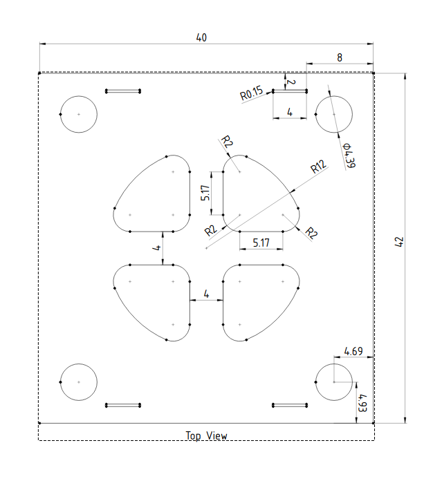
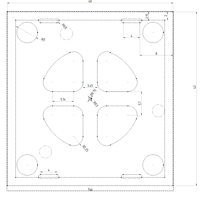
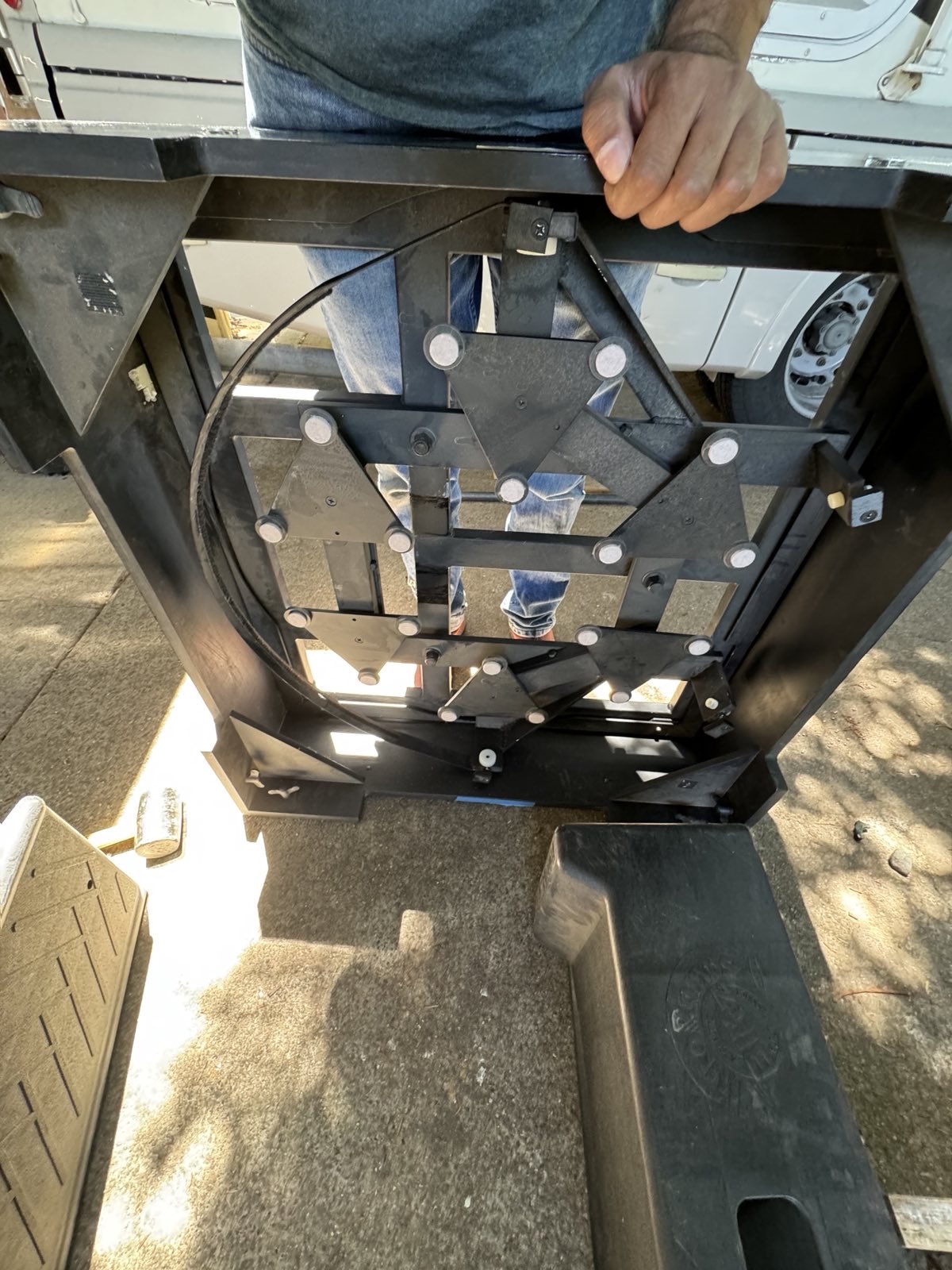
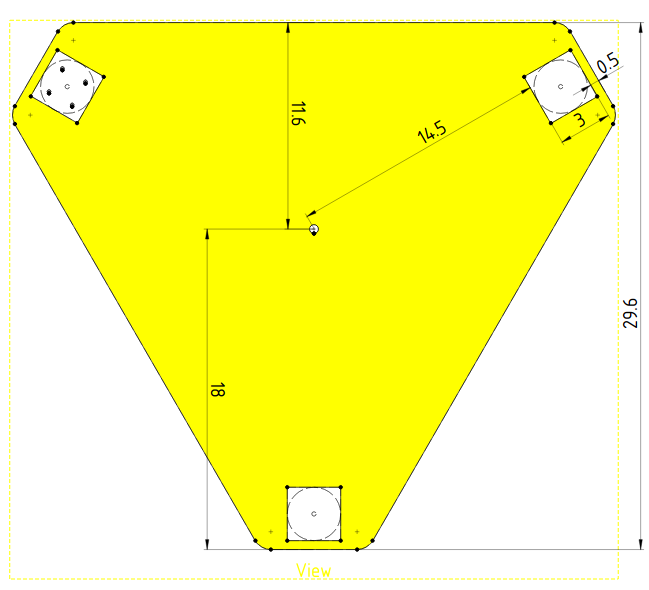
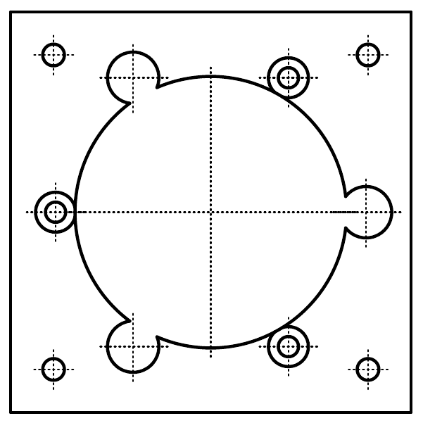
Mark Wagner offered to cut holes for me in the wood on a CNC router for weight reduction. This plan started with a CAD drawing made in FreeCAD. I had to figure out where and how to place the holes to be carved out, without compromising the structural rigidity. My friend Sanath Kumar who has lots of experience in this domain said that around 2" wide beams should be plenty. For good measure, I kept even more width. See the attached drawing for my plan. This was expected to reduce about 15lb (6.8kg) of weight, reducing it from 84lb (38kg) to about 69lb (31kg). In addition to the holes for weight reduction, I included four slots to pass a ratchet strap / tow strap into in order to be able to tug the telescope around or lock the altitude using a ratchet strap. We later used this to assemble the telescope.
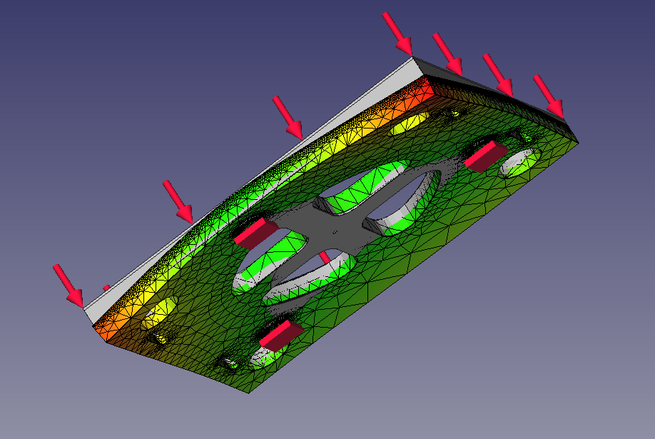
Because of my lack of intuition for strength of materials and my background as a physicist and engineer, I wanted to learn to simulate the stresses in the wood and see for myself how the wood would bend or where the stress would be the highest. Unfortunately, a typical physicist's training largely glosses over the statics of non-rigid solids beyond explaining the relationship between stress and strain through the Young's modulus, Bulk Modulus and Shear Modulus; and, at a higher level, pointing out that the stress is really a tensor. Therefore there is a lot left to learn here and I'm jotting down some of my learnings.
Materials exhibit elastic behavior, i.e. deform under stress and return to normal when the stress is reversed, only when the stress is under an amount called the yield stress. Beyond this, there is irreversible plastic deformation. If the stress is even higher and reaches the breaking stress, the material fractures. A good summary of this concept is here.
Wood is an orthotropic material which means that unlike an isotropic material which has the same elastic properties in any direction, it has three perpendicular principal axes along which the properties are different. There are two elastic properties in each plane that are to be provided to the FEA software: the Young's modulus (E) and the Poisson's ratio (𝜈). The latter quantity indicates the ratio of the strain in the direction perpendicular to the stress, to the strain in the direction of the stress. Due to the orthotropic nature of wood, it has three elastic moduli along the three principal axes and three Poisson's ratios in the three principal planes. Conveniently for plywood, the three principal axes coincide with the three directions of the plywood sheet. This 2022 paper tabulates the properties of birch plywood (Table 1), and provides Stress-Strain curves (Figure 6).
FreeCAD's FEM workbench does not provide a user-interface to handle orthotropic materials, but the underlying CalculiX engine that it uses does support it. This YouTube tutorial explains how to input the elastic properties into CalculiX by manually editing the input file written out by FreeCAD. The following block adapts the data from the aforementioned paper into CalculiX, assuming that the z-direction is along the thickness of the plywood:
**********************************************************
** Materials
** see information about units at file end
** FreeCAD material name: BalticBirch-ThicknessAlongZ
** MaterialSolid
*MATERIAL, NAME=MaterialSolid
*ELASTIC, TYPE=ENGINEERING CONSTANTS
9400,6700,1110,0.034,0.431,0.439,610,206
186,300
*DENSITY
6.93E-10
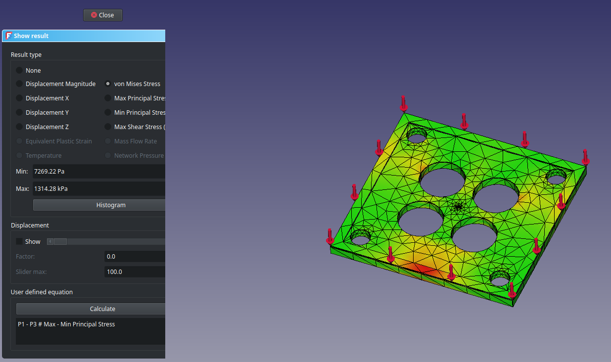
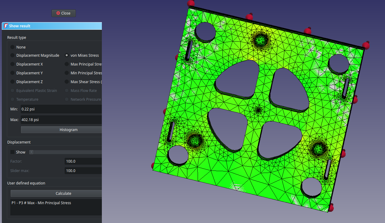
I still am not fully familiar with the various criteria used to assess the stress, but the von Mises Stress criterion seems to be a popular one. I wanted to ensure that the von Mises Stress was under the yield strength of the plywood and verify that the deviation would be minimal. The simulation was a bit hard to get right with the meshing often being improper, but eventually I was able to verify this outcome.
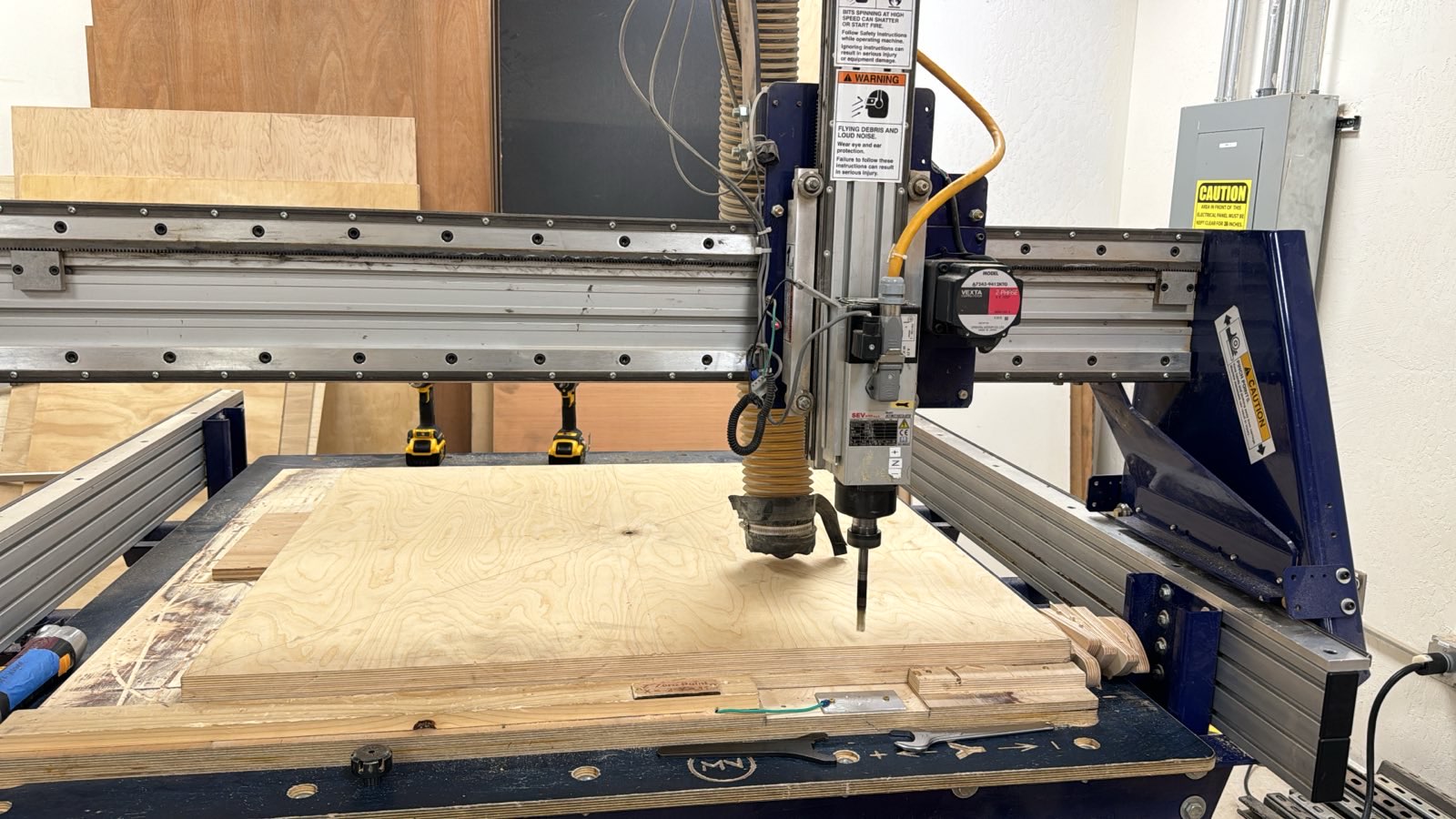
We needed a router bit with a long cutting length capable of handling the 2" thick plywood. We were able to get away with borrowing a 6" bit from Owen, one of the very knowledgeable folks at MakerNexus. We had to be careful to ensure that the router bit would not encounter the hard bronze bushing making the center pivot by accident.
CNC routing: Tack down the wood so it doesn't move. Do an air pass without the bit. Check the zero position properly and check where the bit lands before cutting. Be in reach of the emergency stop.
Lesson learned: Account for router bit diameter
I took the wood to MakerNexus (the maker-space) and Mark helped me load it onto the CNC router bed, and tack it down in place so it wouldn't move from the force of the router bit: we placed various blocks into which we drove wood screws as stops. We did not have a lot of time on hand and wanted to execute on the routing efficiently. Mark pointed out to me that I had not accounted for the router bit size in the CAD drawing. Oops! Mark set up the tool paths and cutting settings for me based on my CAD drawing — we would make 3 passes with the bit for each cut, thereby removing about 0.67" thickness of wood on each pass. Despite our diligence, we had some issues getting the router to know the right depth since the router we used is based on open-loop stepper control, i.e. it does not have any feedback mechanism to find out the true position of the bit. The bit once lost its Z-position because it exceeded the Z-travel due to the 6" long bit, which resulted in the bit dragging on the wood to make a mark instead of moving in the air. Mark quickly noticed this and aborted the operation. The error is only of aesthetic importance and it will make for a good channel for my motor wires when I motorize the telescope :-D.
Because of not accounting for the router bit's size, I ended up with holes and slots that were larger than my original CAD. But this is the good thing about designing with a lot of margin for error: it would be fine any way. So that I have proper documentation for future, I measured these new dimensions carefully and entered them into my CAD model so that it reflects the real part. I also re-ran the FEA and verified that the stresses were still within limits. In fact, because the corners had larger radii of curvature, the peak stress went down! The larger bored holes made the weight lower as well. So it was a good mistake!
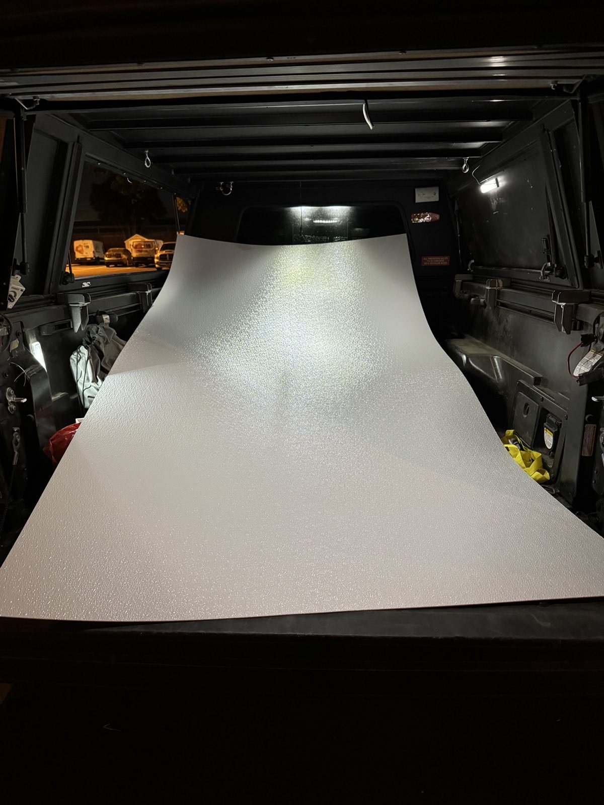
I procured FRP Wall Panel from Home Depot to create the azimuth bearing surface. This is the standard material used on Kriege-style Dobsonians. Unfortunately, it is sold only in 4' × 8' sides and is extremely floppy, and Home Depot will not cut it — it was not pleasant to move from the store into my truck. However, FRP is fairly easy to work with. Keeping in mind that it is fiberglass, I always wore protective goggles and an N95 respirator when working with it. The dust can be very itchy since it has sharp glass fibers, so one is better off with gloves. The trick to cutting the pebbled FRP board is to measure and mark on the back, and cut with a hand saw starting on the back surface. It is possible to also score it and break it, but I was unsuccessful in getting this to work. I made two cuts with a hand saw, creating a 36" × 36" square—more about the azimuth bearing choices in the section on the ground board. The sharp fibers sticking out after the cut are unpleasant, and so I used sand paper to sand it down smooth. I then marked the position of the center of this piece. In this case, it did not have to be exact. Using a larger (than ½"; can't remember exactly which one I used, probably 1.25".) spade bit, I made a rough hole in the center of the FRP and sanded the sharp edges away. I can't recall if I used a wood 2×4 to back the FRP or not, but the precision of this hole was less important: even if I chose to use a center pivot teflon pad, I would use a 3" × 3" one so it would get enough surface area. The larger hole allowed me to accept misalignments with the one-shot glue job with contact cement.
I then used Olympic Waterguard wood sealer spray according to the instructions on the can to weatherproof the wooden rocker box base. I was wearing an N95 mask and performed this in an outdoor environment and avoided breathing the aerosol. After the wood-sealer had done its job, I placed the FRP on the bottom surface of the rocker box to get a rough alignment between the centers of the pivot hole in the rocker box base and the FRP. To mark this alignment, I used painters tape on the four edges of the FRP square.
Since contact cement is unforgiving, I practiced laying out the FRP within the painters tape marks a couple times. Once I felt reasonably practiced, I sprayed 3M contact adhesive on both surfaces as per the instructions on the can, still wearing a mask and working in an outdoor environment. After checking the tackiness of the adhesive as described on the can, I tried laying the FRP on the rocker box base as carefully as possible. Unfortunately, I messed it up, but thankfully the contact cement gave me a second chance—I was able to rip apart the partially glued FRP, readjust it and lay it back down correctly. That was it — no more second chances, but this time I had a proper alignment. The larger hole in the FRP allowed me enough leeway despite the alignment not being perfect. If I were to do this again, I would take a second person's help.
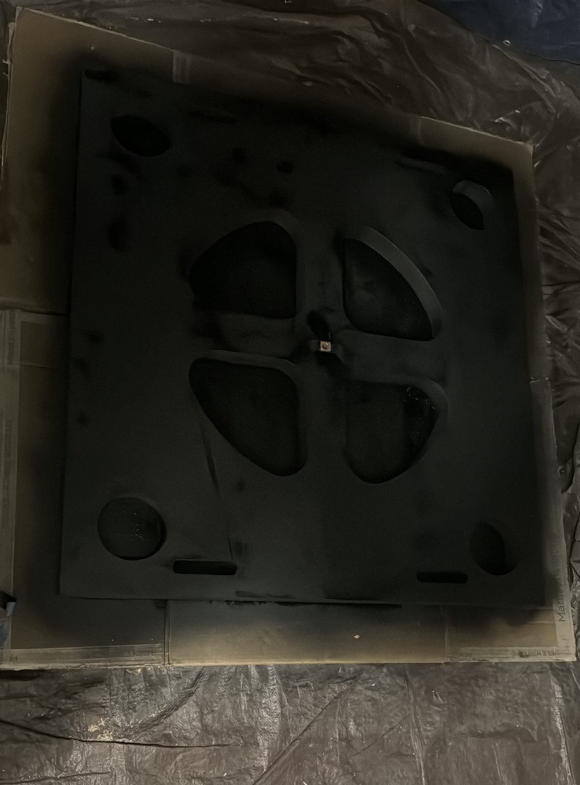
Once this process was done, I laid the rocker box base on its bottom on a tarp with an old cardboard box on it and spray painted the top surface and the sides using flat-black spray paint. The spray paint did get onto the back of the FRP board through the holes cut out, and this was desirable to prevent stray light. I did not bother cutting out the FRP board through the holes as it was immaterial to the function.
Next up was the ground board. I decided to make it out of cheap, nominally ¾" thick plywood. The strength characteristics did not matter as much anyway; see Kriege and Berry §10.2.1 for a discussion. However, Kriege and Berry emphasize that for the large telescopes (see §10.2.2), they make a 1½" thick ground board so that the central teflon pad, which is essential for smooth motion, can take some of the weight of the rocker. Unwilling to add any more weight to the telescope, I decided to ignore this recommendation and live with the less-than-ideal azimuth motion, finding other solutions (such as running a steel channel to give rigidity to the ground board) if it truly bothered me. With just 3 teflon pads, the motion is not convenient, but it has not been unusable.
Kriege recommends that the teflon pads ride under the edges of the rocker box where the weight is transferred from the telescope. But this appeared not to be a hard requirement and I chose to restrict myself to 36" × 36" for simplicity, which is the size I cut the FRP to. The 2" thick rocker box base easily transfers the load without substantial deformation, as proven by the finite element simulation.
Using the formula in Kriege's book, I estimated that 3" × 3" teflon pads would be good. The radius of the circle traversed by the teflon pads on the FRP was chosen to be 16 inches, so that the 3" × 3" teflon pads would fit comfortably in the 36" × 36" wood. Kriege explains the trade-off between a large radius of the azimuth bearing (needed for stability) and the associated friction. The round figure of 16 inches seemed "reasonable" to me.
Mark Wagner offered to also cut the ground board with the CNC router, so I made a CAD drawing for a Kriege-style triangular ground board. It would reduce its bulkiness and look cool!
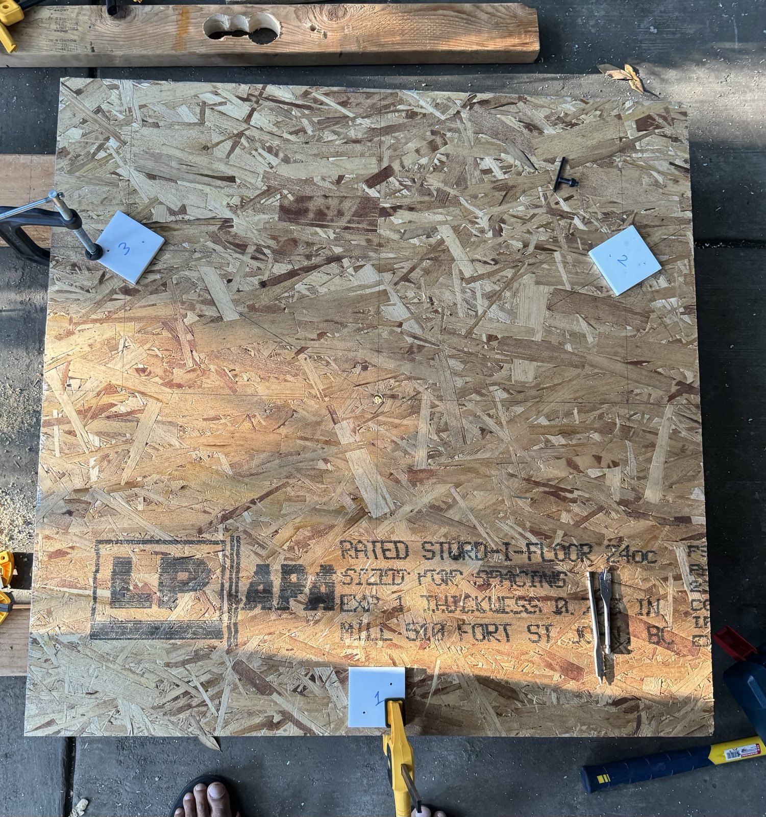
The ground board started as a 23/32" thick oriented strand board. The OSB was the cheapest plywood I could find that had a reasonable thickness (about ¾"). This choice was made purely to keep the price low and keep things simple. The main downside of OSB is that it can chip and lose aesthetics as well as structure. I decided not concern myself with these downsides because the ground board is intended to be replaced with metal when I get the telescope to track. I got the OSB cut to 36" × 36" on the panel saw at Home Depot, the two cuts included in the price.
Because of the tight timeline of the project, I wanted to prioritize required steps over optional steps. The triangular shape of the ground board was optional; in order to not block the required steps on it, I went ahead and drilled the center pivot hole of ½" using a spade bit. I followed the same procedure: multiple measurements, marking, checking the mark, using a small nail to create the divet, followed by a ⅛" pilot hole, and then the ½" spade bit. I also measured and marked the positions for the teflon pads and the feet with tiny drill holes, keeping in mind that the feet must be centered as well as possible on the teflon pads. I did some trigonometry to find the positions of the teflon pads, and I found this method to be more accurate than using a protractor. This was a great exercise in "doing things right".
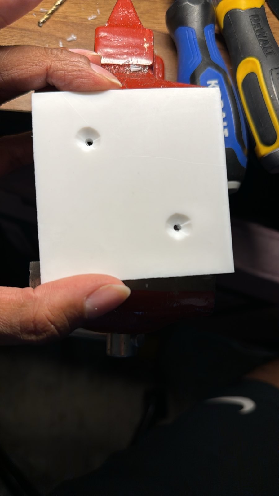
I purchased the teflon from Mark Wagner, who cut four 3" × 3" squares for me on a table saw. Mark's teflon is ¼" thick, which is convenient for using flat-head wood screws instead of the more complicated acid etching + adhesive to mount them. I marked a diagonal of the pad and marked two symmetrically placed points about the center of each square pad. I started these out with small pilot holes and then worked up to a tight clearance hole for a #10 wood screw. Drilling teflon is tricky business, and I had to be careful as the drill bit forms threads that pull the drill in. Then I countersunk the wholes, testing with a #10 flat-head wood screw and a straight edge to ensure that the head would sink below the surface of the teflon. Once one pad was done, the others could be marked easily by lining them up.
Then came the day for CNC routing. The routed dimensions were perfect, but did not center on my bolt hole despite my best efforts of thinking about the cut and the orientation to place the board in. Oops. But not a big problem — I had already learned how to do the dowel fix! I once again wallered the old hole out and pushed the 5/8" dowel through, filling the hole. Marking the correct position of the center hole was tricky now: I could not measure the mid-points of the filleted corners exactly because of the fillets. I eventually figured out a very good way: I used a carpenter's square to draw perpendiculars to the three flattened corners of the triangle without worrying about them going through the midpoint. Then I measured and marked off the 18" point on these three perpendiculars. Then I drew three perpendiculars to the lines through their 18" marks, once again using the square. To my pleasant surprise, the three lines intersected, indicating I had found the centroid of the structure. I drilled the bolt hole there. The ground board was then weather-sealed with the same spray sealant (Olympic Waterguard).
Finding the positions of the teflon pads was now easy: since I had the centroid, I could now draw perpendiculars to the mid-points of the flattened corners without being thrown off by the fillets. I was then able to mark off the centers of the feet, 2" from the filleted edges along those lines. I then constructed and marked a square around this point to represent the boundaries of the teflon pad. Aligning each teflon pad in its square, I clamped it and marked the screw centers using a nail that snugly fit into the holes in the teflon. Then I used that mark to drill the pilot hole for the #10 wood screws part-way through the OSB. The pilot holes were protected with painters tape before painting, so that I could see them easily after. I also drilled small through holes (⅛") for the feet centers so I could see the mark from the other side.
Kriege's recommendation is to make the feet of the ground board from left-over 3" × 3" × 1" plywood. I instead got a 2×4 piece of pine "project wood" and drilled circular feet out of it with a 3" hole saw. It took me a while to learn to use a hole saw properly—I find that it is better to run it on the high speed setting where the kickback is lower, or if using the low speed setting on the hand drill, engage the torque collar to prevent the drill from injuring my wrist. All through, I braced for kickback against my feet. It's important to try to do the hole cutting in one clean run, but it's not the end of the world if one has to stop and start, just the alignment must be good. At the end, I had 3" circular feet of 1.5" thickness (a 2×4 is actually 1.5" × 3.5" in size!). They weren't perfect because I did not run the hole saw straight, but it would not matter anyway as long as the wood was flat from the store. I visually centered these feet over the drilled hole marking their positions, clamped them in place, and used two deck screws each (#8, about 2" long) to fasten them to the ground board. The ground board was then painted with the same flat black spray paint, and I attached the teflon pads to their positions determined by the pilot holes, using #10 flat-head wood screws of ¾" length. Recall that the hole markings were preserved with painters tape.
The final step was to attach the ½"-13 screw-on tee nut mentioned earlier. Unlike the AstroSystems or AstroGoods pivot, I chose to have the flange of the nut pointing downwards and did not use a lock nut. This is not ideal, but I imagine the friction reduction afforded by the bushing will prevent the nut from unscrewing. I centered and ensured perpendicularity of the tee nut by screwing it onto a ½" bolt passed through the ground board, similar to what was done for the bronze bushing. Once the tee nut was flush, I directly drove #8 wood screws through its holes and then un-did the bolt. This finished the ground board, and we had a working azimuth bearing that I tested by standing on the rocker box base attached to the ground board with the center bolt and trying to spin. It was stiff—I had ignored the central teflon pad—but not impossibly stiff.
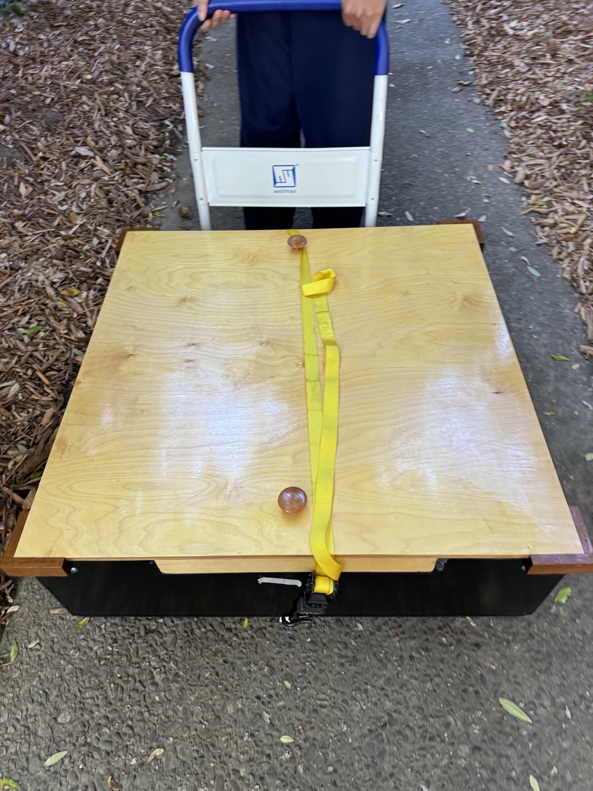
It was time to set up the altitude bearing—the hardest part and home-stretch. For the first time since it arrived from Texas, it was time for the mirror box to leave my apartment. Andy and I loaded the mirror box into the truck. We purchased a used foldable hand cart for this purpose on Facebook marketplace. We ratchet-strapped the mirror box to the cart for stability—the cart was only 24" in length but the mirror box was 32.5". With two people, the mirror box is not difficult to lift albeit unwieldy. Planning and communication is critical for safety.
I drove the whole telescope to Randy Pufahl's house. It's nice to have very experienced telescope makers within a half hour's drive. This was perhaps 4 days before the start of GSSP! Randy had a whole lot of packing to do to get on the road for GSSP, but he still forked out time to help me, for which I'm immensely thankful! We worked for seven hours non-stop and got the altitude bearings working.
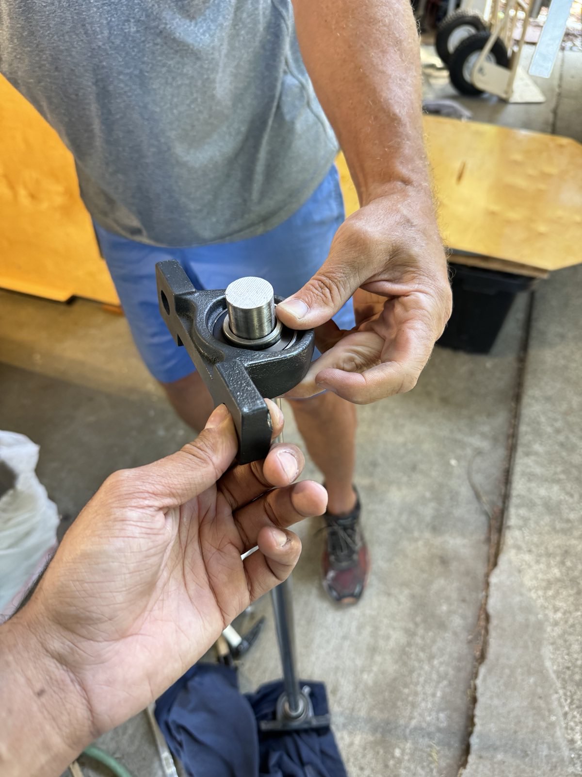
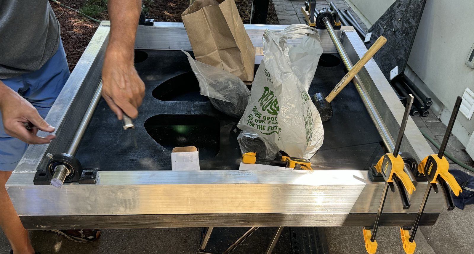
The first step was to lift the mirror out of the box and place it aside, properly covered. Handling the mirror is nerve-wracking but the estimated 100lbs is not difficult with two people. We then drove the stainless steel shafts into the pillow block bearings. The pillow block bearings I purchased from Grainger were expensive and overkill for this purpose, considering the shaft RPMs are utterly low compared to design. I was reluctant to return them and buy cheaper ones due to the tight timeline of the project. The shafts took a little bit of hammering because the remnants I purchased were not TGP shafts — one of them was slightly larger than 1" in diameter. The shafts fit eventually and we measured the appropriate distance between the bearings (42" between centers) before tightening down the set screws.
After this, we marked the expected position of the pillow block bearings as per the calculation made earlier: if the bearing centers had to be 31.5" apart and each bearing had a length of 5.5" according to the specs, the total distance between the distal edges of the bearings must be 37", or their edges must sit 2.5" from the edge of the 42" frame. This calculation was also visualized and verified in FreeCAD earlier. We then clamped the bearings at this position using trigger and screw clamps and adjusted them checking the measurement with a ruler. This provided our starting point. Then assembling the trunnion with the empty mirror box, we rocked the assembly back and forth to check the left-right movement of the trunnions.
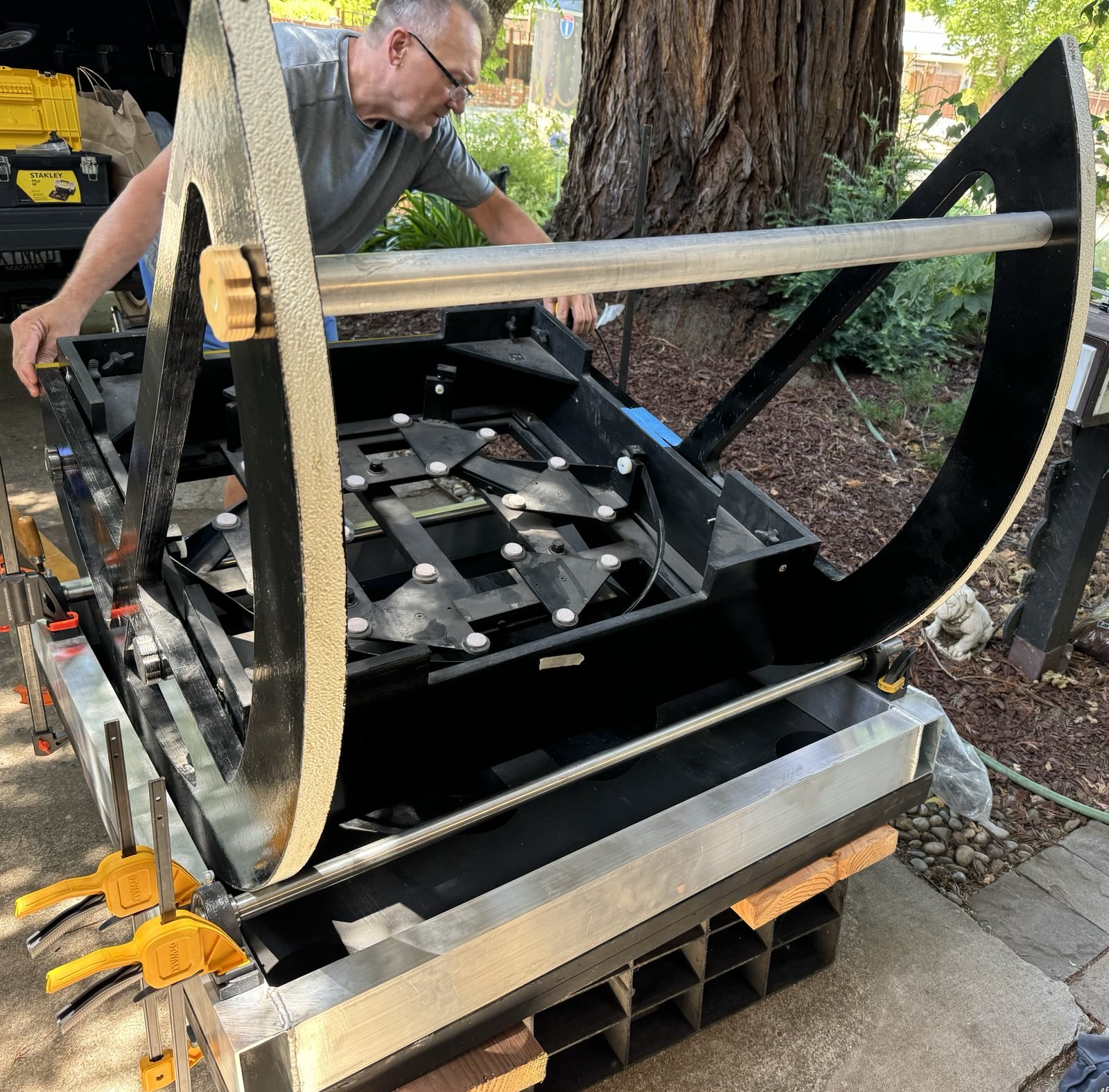
If the shafts are perfectly orthogonal to the altitude axis (as defined by the trunnions), there should be no sideways movement of the rocking parts. Our initial positioning had substantial left-right movement. Orthogonality of axes is important for an encoder-disciplined go-to system. The way Randy checked this on his go-to telescope was to use a laser and have the telescope point to a vertical mark at the wall—when the telescope moves up-down in altitude, the laser should track the vertical line. For the initial hand-operated telescope, this was not as critical, so it was sufficient to eyeball it. Moreover, getting this laser test set up to work with a 28-inch f/4 is not as easy!
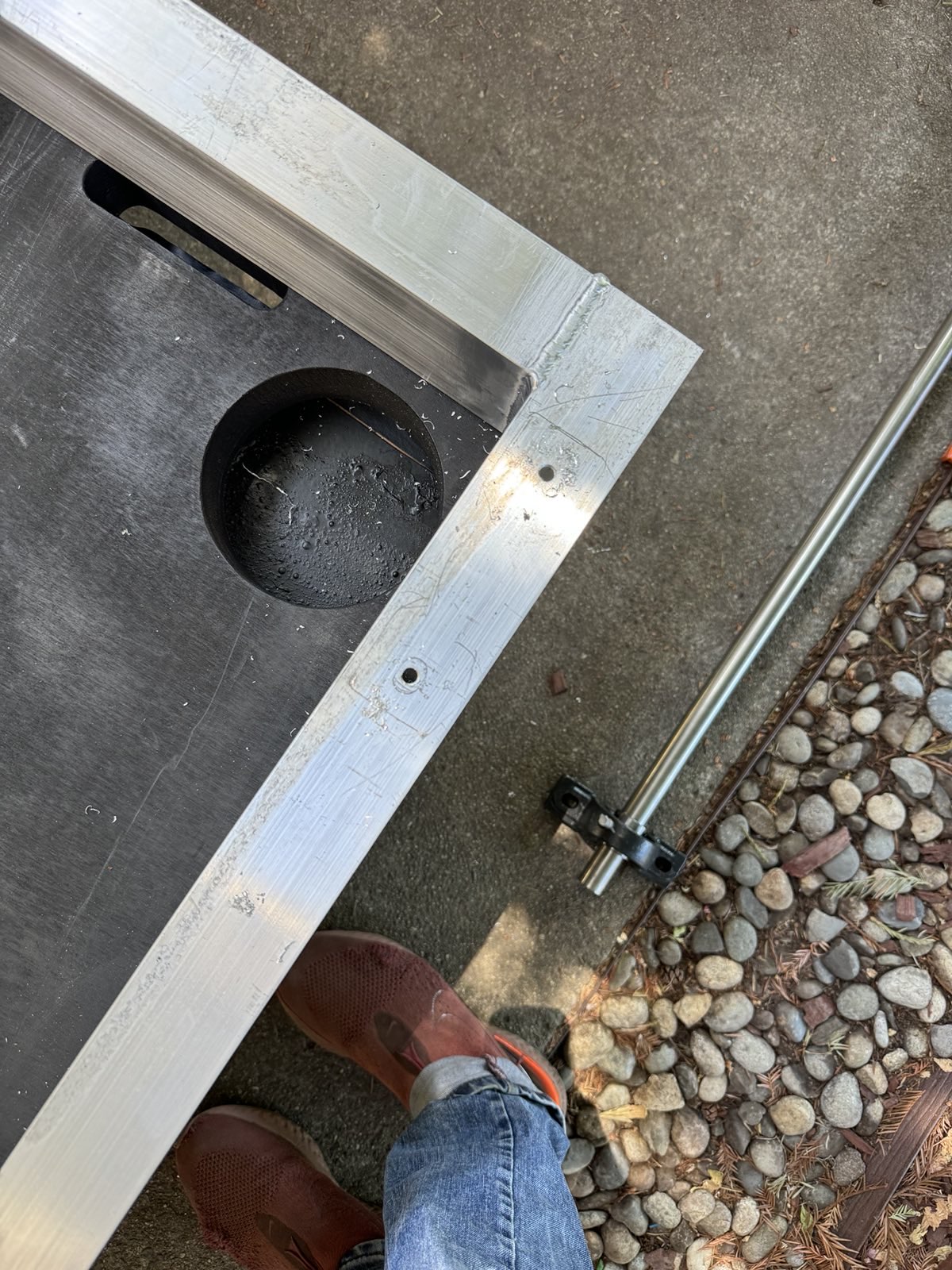
When we set up the rocking parts at first and ran them back and forth, they seemed to deflect in a strange way. Randy quickly guessed that the trunnions were not sitting parallel to each other and with a quick measurement, he identified the cross-strut as needing a bit of shimming. Randy made a fix faster than I could think—using an appropriate-sized hole saw, he cut a washer out of a piece of wood of appropriate thickness. Fastening the wood along with the strut resulted in a parallel pair of trunnions! Once we were satisfied that the rocking parts were running true (i.e. up-and-down without substantial left-right), we marked the positions of the holes using a pencil. It was then time to go buy some screws.
Key takeaway: allow for adjustments of the orientation and position of shafts by choosing smaller fasteners.
Key takeaway: Always try your pilot holes and screws on test materials that mimic the real set up, before drilling the actual holes. Even more so when drilling blind holes that you can't watch.
A key insight I learned from Randy, is that I should allow for adjustment and imperfections. With my physicist-style thinking, I was hoping to find the exact centers of the holes "by mathematics" and using ½" fasteners that matched the pillow block's slot width. In retrospect this was foolish—no real system is perfect. Randy advised me to use smaller fasteners and washers—we would use 5/16" bolts to hold down the pillow block bearings, with appropriately sized washers to spread the force from the bolt head out on the flange. This would allow us to trim the positions of the pillow blocks in all directions. Like in Howard's scope, we were going to tap the holes so that we would not need nuts. Nuts would be a pain to thread on through the narrow aluminum tubing, and would also protrude into the tubing's channel preventing the ability to use a 2×4 inside it for wheelbarrow handles (the way Howard does with his scope).
I was not sure if the threads in ⅛" thick aluminum would hold, and Howard reassured me over an e-mail. It generally takes 2½ to 3 threads to hold a bolt properly in place. I was concerned that if I used the ASME standard "coarse" (UNC) thread for the 5/16" bolt which is 18 threads per inch, I would end up with less than 2½ threads. I realized though that this was not a bolt subject to substantial tensile load -- it was only there to hold the pillow blocks down in place. Thread engagement I imagine matters a lot more when the tensile forces are serious. If I instead use the fine (UNF) thread of 24 threads per inch, I could find myself in the difficult situation of hunting down a fine-thread fastener in a small town if I were to ever lose a bolt. Randy supported the conclusions and we went with standard 5/16"-18 bolts. They have worked fine so far, even when we lift the rocker box by the stainless shafts.
At the hardware store, we purchased 2"-long self-countersinking deck screws and 5/16"-18 zinc-coated bolts 3/4" long I believe (based on the flange height of the bearings). We decided to mount the wooden rocker box base to the aluminum frame using the deck screws first, before mounting the pillow blocks, as we would need to flip the rocker box and it would not be stable on the steel rollers. Once again, we wanted to leave the hollow channel of the aluminum tubing relatively undisturbed to use for wheelbarrow handles. This meant that we would drive the fasteners along the shorter side of the rocker box, through the tubing whose ends were welded. Because we could not see the screws going through, Randy first ran a couple tests. First, we drilled pilot holes and deck screws through similar pieces of wood and aluminum to figure out what size the pilot would need to be, sacrificing a deck screw in the process. Once we found the best-fit pilot drill, we drove a couple test screws into the part of the tubing we could see, just to get an idea of how deep the head needed to sink into the wood for the screw to pierce the aluminum. We adjusted the torque collar on the hand-drill to ensure we would drill to this depth and stop. Once we had this figured out, we marked 3" intervals along the center of each 36" long aluminum tubing and drilled pilot holes and deck screws into them, fastening the base to the frame. The base was clamped to the frame at multiple locations to hold it still during this process.
Now it was time to drill and tap the pillow block bolt holes. I believe we used a center punch to create the divets, and started the holes with a small drill, working our way up slowly to the tap drill for 5/16". Randy pre-tested the tap drill on similar aluminum. We then tapped the holes.
Once the holes were tapped, we mounted the pillow block bearings roughly centered in the slot, and gently tightened the bolts. Once again testing the altitude movement of the rocking parts, we used a hammer to reposition the bearings until we did not see substantial left-right movement. Once the positions were determined, we marked the outlines of the bearings with a pencil. This was useful in detecting an accidental movement of a bearing before we tightened it down, so we were able to fix it! We then used a socket wrench to tighten the bolts down really nicely. While testing the altitude movement after this, we quickly realized the importance of having trunnion stops at least at one of the ends, and Randy quickly made one out of scrap steel before we placed the mirror in! This ensured we didn't accidentally drop the mirror box from the rollers!
To make the trunnion stop, Randy quickly cut a piece of steel into two using a reciprocating saw, drilled a couple holes in each one, and fastened one of them with deck screws to a trunnion. To ensure that they would engage simultaneously, he pushed the altitude assembly to its limit after affixing one of the stops, before installing the next stop in a manner so it would make contact.
Somewhere along this process, we realized that the pronged tee-nuts which were used to allow the bolts to hold the trunnions to the mirror box were coming loose. Randy looked at it and explained to me that we should place the tee nuts in such a way that the force of the fastener pulls the prongs into the wood when tightened. So we moved the T-nuts on the inside of the mirror box, and hammered them to help get them started before placing the mirror! Then we threaded and tightened bolts into them to pull the tee nuts in place.
We placed the mirror in the mirror box, and packed up for the day. The two of us carefully lifted the mirror box with the trunnions onto hardwood 6×4s, removed the trunnions, lifted the rocker box into my truck and then the mirror box. With this we were almost ready for zeroeth light.
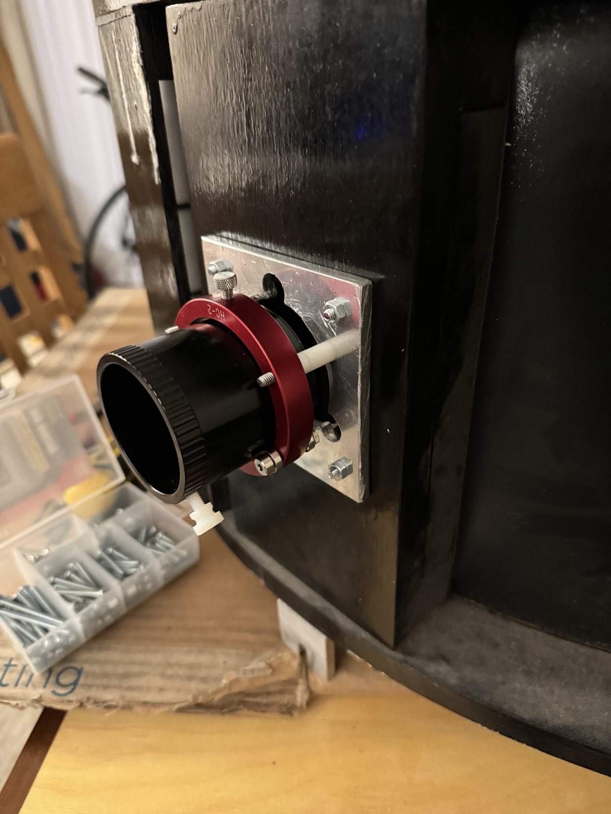
Jimi Lowrey had salvaged the focuser he used on the 28-inch for a different project. I purchased a 2" Helical Crayford focuser (HC-2) from Joe LaCour at Kine Optics. This focuser has a very simple and extremely light-weight design. The quality of manufacturing is very good. My only issue is that I haven't gotten used to using it correctly, and I think I prefer a standard Crayford focuser on my large aperture dob. For this reason, the focuser may eventually end up on a light-weight travel dob instead; but for now it works fine and only needs some spacer adjustments.
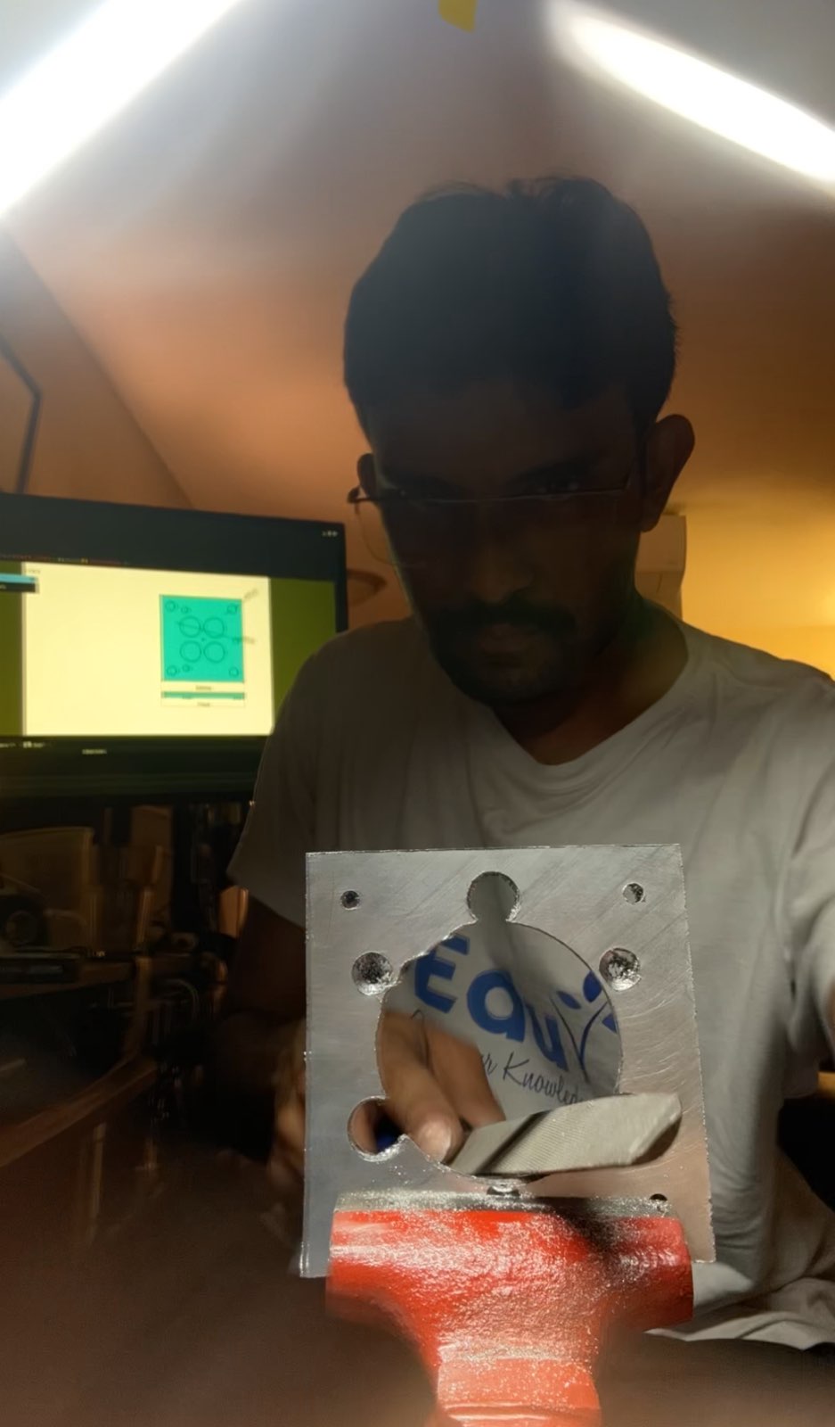
In any case, the secondary cage had a square pattern of holes, 2.75" in side, drilled out to match a Starlight Instruments focuser. I had to adapt it to the HC-2. Initially I thought of making a 3D printed adapter plate, but thinking of the weight of a 31mm Nagler hanging off a 3D printed part was unsettling. What if it gave way and the eyepiece fell? Perhaps I was overthinking, but I wanted something solid. So I decided to make this adapter plate out of aluminum; it was also going to be an interesting exercise in making a part, going from CAD design to finished product, by hand! I most certainly enjoyed this process, even though there were clearly simpler designs that would work.
The HC-2 has a pattern of three #8-32 screws placed 120° apart on a circle of diameter 2.715". Since my measurements were not entirely accurate, I obtained a drawing from Joe LaCour to determine this. The catch was that the circular hole made for the drawtube of the Starlight Instruments focuser was close to or larger than (2.715 - 0.175) = 2.54 inch in diameter, where 0.175" is a decent-sized clearance hole for a #8 screw, so I could not simply drill new holes in the existing setup. The easiest path forward would have been to place a few mending plates on the back of the mounting board and drill holes in the plates. This did not hit me until I had finished this more complex design, but I did have fun making this complex part so it's all good.
The plate started out as a remnant ATP-5 material ¼" thick picked up at Industrial Metal Supply Co. ATP-5 and Mic6 are tooling plates which are designed to have a high-degree of flatness, ideal for a focuser. What I did not know at this point is that the focuser mount must allow for tilt adjustment! I made the mistake of assuming that the wooden backing would be true, and that as long as the plate was flat, the focuser would be held parallel to the optic axis. I should re-emphasize the lesson in my head—only in theory is everything perpendicular! So the ATP-5 wasn't really necessary, but it wasn't that much more expensive than standard aluminum since the remnants are sold by the pound. The damage for a large plate that can be used for other projects was around $20.
I went with a ¼" thick plate because I thought it would be needed to support the weight of the focuser. This was stupid in retrospect. I could've gotten away with 3/16" or likely even 1/8" thick aluminum which would have been way easier to work with. Throwback to engineering college, the dreaded "Fitting Workshop" had us cut mild steel about ¼" thick with just a hack saw, and file it down to dimension by hand. Thanks to this character-building experience, I knew that ¼" thick aluminum was well within manual capabilities.
When I did any machining in graduate school for work in the Raizen lab, it was with Bridgeport mills with digital readouts. Using imprecise hand-tools to do a precision job was going to require a different approach. The most crucial aspect was getting the triangular hole pattern for HC-2 centered in the square hole pattern for the Starlight Instruments. To facilitate this, I took a laser print-out of my CAD drawing to-scale and transferred the drawing using acetone onto the aluminum plate, as explained in this YouTube video. It's important to remember to flip the drawing as the paper goes face down on the metal, but my drawing was symmetric so this did not matter. The other important thing was to mark the center lines for the holes; FreeCAD's TechDraw workbench provides an option to do this.
With the hole positions now marked on the aluminum, I could easily center the holes accurately. To drill the holes, I started with a center punch and worked up from small drills to big drills. So that I only had to saw two sides, I positioned the drawing at one corner of the ATP-5 plate. I used a second plate of ATP-5 to provide a place for me to rest my drill guide. The two ATP-5 plates were clamped to wooden bars to keep them in place while I worked. I still got the holes a bit off, because I did not make proper divets. Yet, they were close enough that the holes worked perfectly.
The HC-2 has tapped holes for #8-32 screws, so my part had clearance holes instead. I added a counterbore in my design so that the (button) heads of the #8-32 screws would not protrude, allowing the plate to rest flush against the secondary cage. To achieve a poor man's counterbore, I simply used a larger drill bit for a short depth. My counterbore surface is not flat, but I imagine the screw would pull the HC-2 surface flush against the ATP-5 plate anyway. As I mentioned earlier, I should have thought of some mechanism to articulate the focuser axis, but this is not as significant as other aspects of collimation and the telescope is working very satisfactorily without this adjustment. This can likely still be retrofitted. For the 2.75"-spaced mounting holes, I went with #8-32 clearance holes. In retrospect I should have tapped these holes, as this would remove the need to tighten a nut.
The hardest and scariest part of making this plate was to drill a hole for the focuser draw tube. Given that I was not very comfortable with hole saws and the substantial kickback (should've used the torque collar!), this was downright scary! I did it slowly and patiently. Whereas the dimension I wanted was a bit larger than 2.5", I figured I would use a 2.5" hole saw and file the rest. In retrospect, I would've saved myself a lot of trouble by using a 2 ¾" hole saw in lieu of the 2 5/8" which was not part of the kit I purchased. I had to file the 2½" hole quite a bit both due to the imperfections in the edge of the hole, the non-perpendicularity of the hole, and the imperfect centering of the hole. I used a half-round file for this purpose.
Tiny as it may be, this was one of the most satisfying bits of the project for me as I did it all independently from the start to the finish. It gave me a lot more confidence in my ability to make simple parts. I was very pleased when it fit exactly, except for the draw-tube hole: the aluminum having a high coefficient of thermal expansion, the hole would contract under lower temperatures. I filed it a little extra until the draw tube would move in and out smoothly irrespective of the temperature of the plate—I cooled the plate by putting it in the freezer in a Ziploc bag and tested it.
It's customary to put the secondary in a crown royal whiskey bag made of velvet, and then put it in an AstroSystems breathable cover. But knowing that I abuse my equipment, I wanted a hard case for the secondary so I can carry it in the back of my cabin without worrying about protecting the secondary.
Making the hard-case was easy. It started out as 6" ABS sewer pipe which I sawed with a hand saw to dimension. My sawing wasn't perfect and it didn't matter. I chamfered the sharp edges with a file. Then I drilled two opposite holes on one end of the pipe to pass some paracord through. Cutting the paracord and sealing its frayed fibers with a safety lighter, I passed it through the hole and knotted it so it would remain there. This completed the secondary hard case, a quick and easy solution—I simply tie the free ends of paracord together and let it hang from the spider. This is inspired by a hard case my friend Sanath Kumar made for another telescope. I also placed felt furniture pads on the secondary holder so as to create a gap between the secondary mirror and the pipe and give it a snug fit. The pipe was cut to be longer than the secondary, so an end-cap was not really needed.
I purchased a large velvet bag from Amazon as I wasn't sure if a standard Crown Royal bag would fit my secondary. Little did I know that Jimi had already included a crown royal bag, oh well.
I was now ready for zeroeth light. Zeroeth light started with me trying to get some help to lift the mirror. Our first attempt was not safe and was an important lesson in safety when handling heavy objects; thankfully, things turned out okay. The best way to handle a big telescope is to not lift it, and I am working hard on finding ways to make this happen within my constraints.
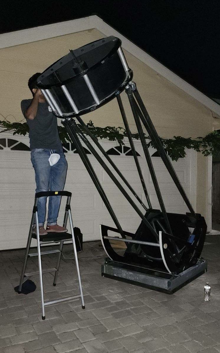
Anyway, three of us—Komal Bhardwaj, Vishal Kasliwal, and myself—set up the entire telescope at Vishal's drive way in San Jose. I had unfortunately left the light shroud at home, so we had to deal with the plenty of stray light of the urban environment. I also did not have a way to transport the ladder, so we decided we would point it close to the horizon, within range of Vishal's household ladder.
Lifting heavy stuff like a mirror box requires careful planning and coordination; one should first talk out the plan to ensure everyone is on the same page
We were surprised that everything worked! Well, almost. We only had two problems. The stars appeared fuzzy, and the altitude motion was terrible. Even though it was balanced and smooth-moving, when one moved and let go of the telescope, the telescope would settle into a position between the pebbly surface of the FRP. This means there was about a ½° backlash, give or take, which made the telescope completely unusable. It was impossible to center Andromeda Galaxy. But we were at the same time in awe at how bright and big M 32 appeared. Overall, the view was terrible because of stray light. In addition to not having a light shroud, we did not have a baffle—Jimi designed the secondary cage to be low profile and light-weight; without a baffle, stray light enters the focuser tube. Most modern portable dobs are designed this way. We also found the azimuth motion was very stiff because I had skipped the central teflon pad, but I was not (and am not) bothered by it to be honest.
We never figured out what caused the fuzzy stars, it was probably just a hot mirror and poor seeing. Maybe improper collimation (we only performed a quick laser collimation) was part of the problem. The stars looked fine during first light with no material change other than centering the secondary properly.
A discussion erupted on how we could quickly "salvage" the altitude movement and make it work. Our original idea was to fasten 3/16" thick pieces of flat aluminum on the trunnions to produce a durable load-bearing surface, but this would require someone to form metal into that shape. Although our local maker-space has the tools, I am not knowledgeable let alone certified to use the equipment. There are several metal fabricators around Santa Clara, but time was limited. Randy Pufahl came up with the brilliant idea of simply sanding the FRP pebbles down. 45 minutes of careful sanding manually with a sandpaper wore the pebbles down on each trunnion's FRP strip. I sanded one trunnion before GSSP at home, and one on the field at GSSP! This is a temporary solution as one would want a harder, more durable aluminum (at least) surface. In fact, some telescope makers have made their trunnions out of steel because even aluminum can gall! But that aluminum trunnions suffice is established by several telescopes that use them.
I needed cross-bars or a roof rack to tie stuff on top of my roof. I learned how to do this from an overlander friend who had researched and implemented his own custom solution based on aluminum extrusion. He was able to point out some key important things to make a secure system, as this is a very important load-bearing system, such as that the nuts should fit absolutely snug in the provided nut slots to allow for both thermal expansion and the shearing of the metal under the strong forces transferred into a vehicle by the road. After a lot of trial and error, I finally found out that my Alu-Cab canopy was designed to take M8 carriage bolts.

One of our respected observing friends encountered a poorly secured chair from the vehicle in front of him hitting his windshield while driving to a star party. We are lucky he made it unscathed, but personal anecdotes like this underscore the importance of a secure system. I've encountered a ladder fall from a truck in front of me while driving on the freeway, luckily I was able to entirely avoid it. Therefore I would rather over-engineer such a system, because the risk of under-engineering is profound. I bolted the 40×40 aluminum extrusion cross-bars to the canopy using M8 carriage bolts and M8 nuts with fender washers, by drilling a through-hole through the extrusion. As an additional safety, an aluminum L-bracket used to join pieces of extrusion was bolted in the front of the extrusion as a "brake" to take off some of the force. The truss poles and the ladder were ratchet-strapped to the cross bars. In addition, I placed a final safety system in the form of a heavy-duty ratchet strap securing the ladder to the frame, so as to "catch" the ladder if I were to ever brake hard. This system was so secure, that the ladder and the truss poles did not move an inch through the entire journey.
Building the system with steel rem-bars from the metal supply would have been cheaper and stronger, but the versatility of aluminum extrusion allows flexibility. In fact, I added two eye bolts to further tie down the truss poles in place, which I simply screwed into square nuts that I dropped into the extrusion slot.
I also learned from Jimi that I was using ratchet straps incorrectly. There is an optimal number of wraps of the webbing on the mandrel, which is between two and four. The lower limit is of course more crucial—there must be at least two wraps. So the correct way is to not wrap all of the "left over" webbing on the mandrel, but to pull most of the slack out and then ensure there are about two wraps of the mandrel when the ratchet is worked. See this YouTube video for example, but one thing that is not emphasized in the video is that threading it is more intuitive with the ratchet closed.
I must of course say that I can't certify my method. I disclaim all liabilities arising out of someone else trying my methods, all I can say is that it worked for me once. If you don't want to assume the liability, go buy a $500 roof rack from a reliable manufacturer like Prinsu! But I will say that there are plenty of people building cross-bars out of aluminum extrusion and mounting much heavier loads on them.
It was most certainly unnerving to do first-light at GSSP, "patching in production" so to speak. But I knew I had a lot of help from very experienced and ingenious telescope makers—Howard Banich, Randy Pufahl, Charlie Wicks, Jimi Lowrey were all going to be there. I packed every tool, every fastener, everything I could think of, and even some spare material like wood, FRP and Teflon. There is also a very good hardware store (the Red Barn) only 20 minutes from the star party, so I knew I would not be in soup if I forgot something that was widely available.
There were only three things we had to do before first light—sand the remaining trunnion, do a thorough optical alignment, and create a light baffle. The sanded trunnions worked very well and we were able to first-light the telescope! With proper secondary mirror alignment, we did not see any fuzzy stars—not sure if that was the cause. The telescope performed as is expected for a 28-inch! So all was well...
...until we discovered it wouldn't hold collimation. Randy quickly figured out the cause—over the 10+ years of sitting in storage, one of the truss clamps had come a bit loose. Once the problem was identified, it was easy to fix. In fact, we fixed the collimation and re-adjusted the secondary mirror in the dark and got the telescope working properly. After that it held collimation just fine!
The views through the 28-inch were amazing, even though there are some issues to address (including re-coating the mirror). This is where the story ends for now.
You can tell from this log that I was greatly helped in this endeavor by several experienced telescope makers and many others. Jimi Lowrey laid down the idea of how we would build the rocker box in three weeks and loaned me his ladder amongst other things. Connie Lowrey was a source of inspiration, encouragement and strength. Mark Wagner and Randy Pufahl helped me with the building tasks as described in the log. Howard Banich stood behind the scenes, giving me encouragement and helping me over the internet. Tom Osypowski lent me his expertise over e-mail with several quick questions. Charlie Wicks helped me do the final optical alignments and loaned me his collimation tools. Tanveer Singh helped me figure out how to use aluminum extrusion. Vishal Kasliwal and Komal Bhardwaj helped me assemble the telescope for the first time and conduct the zeroeth light. Russ Garber and John Hoey helped me assemble the telescope at GSSP. Many many people shared my excitement and looked through my telescope. Andy Nguyen put up with the living room being turned into a workshop, helped me move the mirror box, and continues to put up with the many telescopes that litter our apartment. My mother and brother were sources of support and encouragement, and made accommodations to let me focus on the project.